Version 1.3
| Field | Value |
|---|---|
| Document Title | AWS WireGuard BGP WAN with Automated HA Hub Failover |
| Author | Eric Schmitt |
| Document Version | 1.3 |
| Date of Issue | February 13, 2026 |
| Document Status | Production-Ready (Educational Lab / Proof-of-Concept) |
| Document Type | Engineering Lab Implementation and Validation Report |
| Core Technologies | WireGuard, BGP (FRR), AWS EC2, EventBridge, Lambda, CloudWatch |
| VM Platform | AWS EC2 and VMware Workstation Pro: Ubuntu Server 24.04 LTS |
| Architecture Pattern | Hub-and-Spoke WAN |
| Cloud Provider | Amazon Web Services (AWS), Region: us-east-1 |
| Version | Date | Description |
|---|---|---|
| 1.0 | 2025-12-01 | Initial document draft |
| 1.1 | 2025-12-14 | Validation alignment and terminology refinement |
| 1.2 | 2026-01-25 | Raw data reconciliation and formatting standardization |
| 1.3 | 2026-02-13 | Final editorial revision reflecting current lab state |
This document is intended for technical and technical-adjacent stakeholders:
Network Engineers responsible for WAN routing, encrypted transport, and control-plane design
Cloud Engineers responsible for AWS infrastructure and automation
Platform / Infrastructure Engineers evaluating hybrid WAN reference patterns
Technical Management reviewing architectural viability, resilience, and operational readiness
Assumed baseline familiarity:
IP routing fundamentals and troubleshooting concepts
BGP routing concepts (eBGP adjacency, route propagation)
Linux networking (interfaces, routes, forwarding)
AWS EC2 fundamentals (instances, Elastic IPs, security groups, IAM)
This document uses hub-and-spoke WAN terminology consistently:
Hub: Central aggregation nodes hosted in AWS EC2, terminating WireGuard tunnels and acting as eBGP transit hubs for this lab scope
Spoke: Remote nodes (VM-based) connecting into the hub via WireGuard and participating in BGP for reachability exchange
This terminology is selected to align with common enterprise WAN design language.
The lab device hostnames reflect a spine/leaf naming convention from an earlier architectural design and are retained verbatim for fidelity to the implementation:
| Logical Role | Hostname Examples |
|---|---|
| Hub (Active/Standby Pair) | DC1-SP1, DC1-SP2 |
| Spokes | SITE1-LF1, SITE2-LF1, SITE3-LF1 |
Mapping used throughout this document:
References to hub correspond to
DC1-SPx devices.
References to spoke correspond to
SITEx-LF1 devices.
This document describes a fully functional lab implementation designed to validate an enterprise-style WAN pattern:
Encrypted underlay transport using WireGuard
Dynamic routing overlay using eBGP (FRRouting)
Automated active/standby hub failover and failback using AWS EventBridge and Lambda
Health-based contingency failover using CloudWatch Alarm triggering the same failover Lambda
Although small in scale, the implementation is intentionally aligned with enterprise principles such that it can serve as a baseline for a small-to-medium production WAN with minimal modification.
Out of scope for this document:
Active/active hub routing and per-flow distribution across hubs
Multi-region hub deployments
VRF-based segmentation / multi-tenant overlays
SD-WAN orchestration layers and controller-based policy distribution
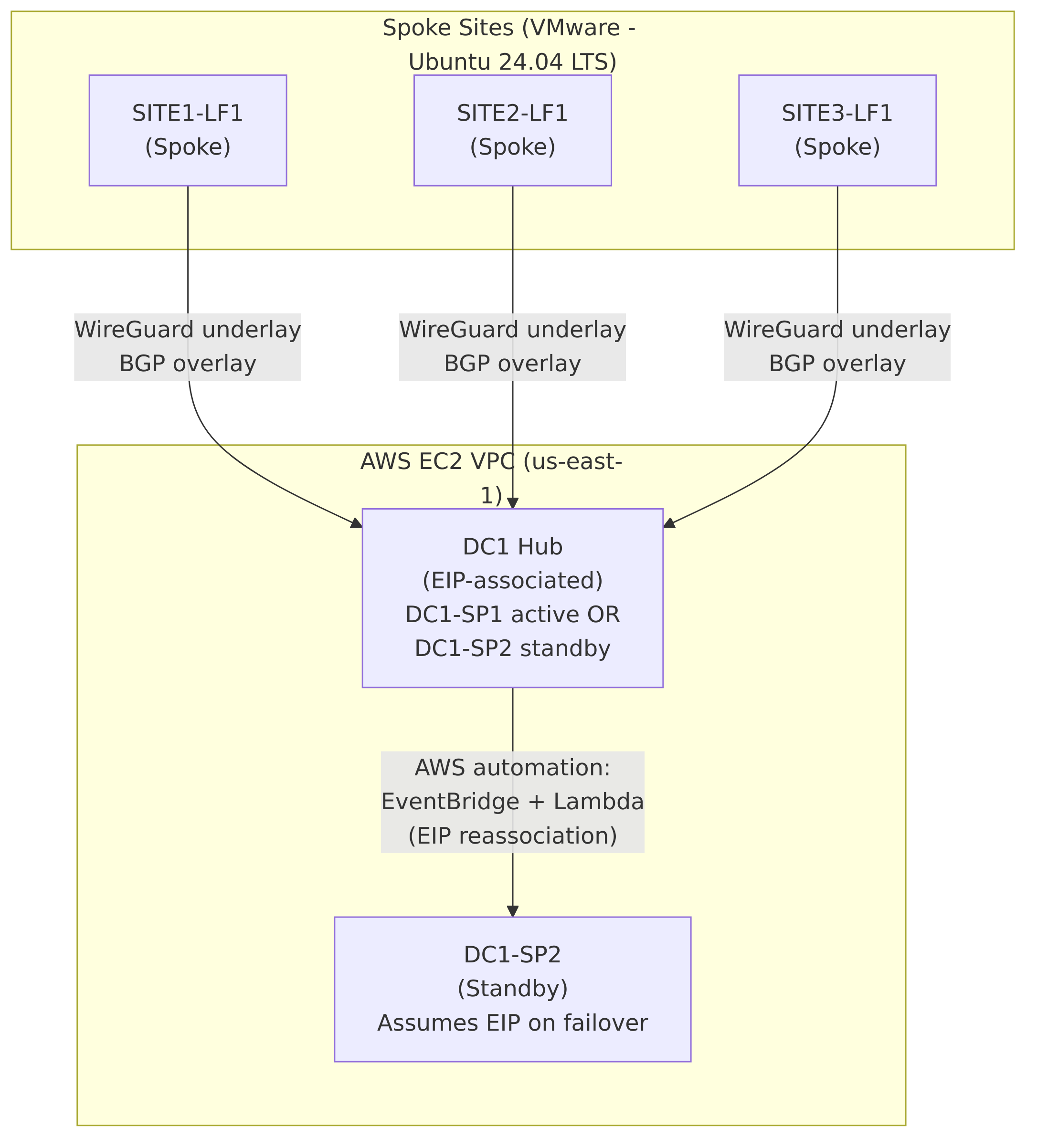
A high-level reference architecture diagram is included later in this document (see Section 4). It illustrates:
Hub-and-spoke topology and addressing
WireGuard underlay termination at the hub pair
BGP overlay reachability exchange for loopback reachability
AWS-controlled Elastic IP reassociation for automated failover and failback
This document describes the design, implementation, and validation of an AWS-hosted hub-and-spoke WAN architecture using WireGuard for encrypted transport, BGP (FRRouting) for dynamic routing, and AWS-native automation for active/standby high availability.
The environment is implemented as a lab / proof-of-concept but is intentionally designed to align with enterprise-grade architectural principles, including deterministic routing behavior, encrypted transport, automated failure handling, and operational observability. While not feature-complete relative to large-scale production WANs (e.g., active/active hubs, VRFs, or centralized SD-WAN controllers), all architectural decisions reflect realistic operational constraints and failure scenarios commonly encountered in small-to-medium enterprise deployments.
The solution demonstrates that a minimal infrastructure footprint—two cloud-based hubs and multiple remote spokes—can deliver encrypted connectivity, dynamic routing, and automated failover without reliance on proprietary SD-WAN platforms.
The WAN follows a hub-and-spoke topology:
Two AWS EC2 instances act as eBGP transit hub nodes (DC1-SP1 and DC1-SP2), configured as an active/standby pair.
Multiple remote spoke nodes (SITE1-LF1, SITE2-LF1, SITE3-LF1) connect to the hubs over WireGuard tunnels.
All routing intelligence is exchanged dynamically using eBGP, with each node advertising a single loopback address representing its logical presence in the WAN.
Only one hub is active at any given time. An AWS Elastic IP (EIP) serves as the stable public endpoint for all spokes. Although both hub instances are configured to advertise the same hub loopback prefix, only the hub currently associated with the Elastic IP is reachable. Automated reassociation of this EIP ensures that spoke connectivity is preserved during hub failure or recovery events without requiring any routing changes on the spokes.
High availability is achieved using AWS-native event-driven automation rather than traditional network-layer redundancy protocols.
Two independent but complementary mechanisms are implemented:
EventBridge-driven failover and failback: EC2 instance state-change events trigger AWS Lambda functions that move the Elastic IP between hub instances when the primary hub stops or starts.
CloudWatch health-based failover: A CloudWatch alarm monitors EC2 instance health checks. When the primary hub becomes unhealthy (even if still running), the same failover Lambda is triggered to move the Elastic IP to the standby hub.
This dual mechanism ensures resilience against both hard failures (instance stoppage) and soft failures (instance running but impaired).
Dynamic routing is handled exclusively via eBGP for overlay reachability:
Each spoke advertises a unique /32 loopback address.
The hub advertises a shared /32 loopback address representing the logical hub service endpoint.
No static routes are used for overlay (inter-site or spoke-to-hub) reachability; all overlay prefixes are learned and installed via BGP.
Underlay connectivity relies on directly connected kernel routes associated with WireGuard interfaces, while all spoke-to-spoke and spoke-to-hub communication flows are determined by BGP-learned routes. This design ensures predictable traffic paths, centralized transit through the active hub, and simplified troubleshooting.
The lab validates the following behaviors end-to-end:
Encrypted WireGuard tunnel establishment and maintenance
BGP adjacency formation and route propagation
Spoke-to-spoke and spoke-to-hub reachability via BGP-learned routes
Seamless hub failover with transient packet loss during Elastic IP reassociation
Automatic failback when the primary hub returns to service
Observed behavior, command outputs, routing tables, traceroutes, and AWS logs are documented in later sections of this report (see Section 6 and Section 5.6).
A high-level architecture diagram is included later in this document using Mermaid syntax (see Section 4). The diagram visually represents:
The hub-and-spoke WAN topology
WireGuard tunnel termination at the hub pair
BGP route advertisement and propagation
AWS-managed Elastic IP failover and failback flow
The diagram is intended as a conceptual aid and does not replace the detailed configurations and validation evidence provided elsewhere.
This document covers the design, deployment, and validation of a hub-and-spoke WAN architecture implemented using open standards and AWS-native services. The scope of the implementation includes:
Encrypted WAN transport using WireGuard
Dynamic routing using eBGP via FRRouting (FRR)
Active/standby hub redundancy using AWS Elastic IP reassociation
Event-driven automation using AWS EventBridge, Lambda, and CloudWatch
End-to-end validation of routing, reachability, and failover behavior
The environment is intentionally minimal in size but complete in functionality. It is designed to model a realistic enterprise WAN deployment pattern while remaining small enough to be fully observable and auditable.
The following items are explicitly excluded from the scope of this document:
Active/active hub operation or ECMP-based multipath forwarding
Advanced BGP policy controls (route-maps, communities, traffic engineering)
VRF segmentation or multi-tenant routing
Automated WireGuard key rotation
Integration with centralized identity providers or PKI
Performance benchmarking beyond functional validation
Where relevant, these topics are discussed at a conceptual level as future enhancements but are not implemented in the current lab (see Section 8).
The primary objectives of this lab are technical rather than commercial. The design is intended to validate architectural soundness, operational feasibility, and automation correctness.
Key objectives include:
Demonstrate a production-aligned WAN architecture using open-source tooling
Validate that WireGuard can function as a routed overlay under BGP control
Achieve deterministic spoke-to-spoke routing via a centralized hub
Implement automated hub failover without requiring reconfiguration of spokes
Ensure that failover behavior is observable, auditable, and repeatable
From an operational perspective, the lab seeks to demonstrate:
Clear separation between underlay transport and overlay routing
Minimal configuration requirements on spoke nodes
Predictable behavior during hub failure and recovery
Use of cloud-native services for availability rather than protocol-level redundancy
Operational simplicity is treated as a first-class design requirement. All mechanisms used for availability and routing are intentionally explicit and observable rather than implicit or opaque.
While this document is primarily technical, it is structured to be accessible to multiple audiences:
Network Engineers: Detailed configuration, routing behavior, and validation evidence
Cloud Engineers: AWS service integration, automation logic, and failure handling
Technical Leadership: Architectural rationale, risk trade-offs, and extensibility
The document is suitable both as a learning artifact and as a reference baseline for adapting the design to a production WAN environment.
The reference architecture implements a hub-and-spoke WAN model using encrypted point-to-point tunnels for transport and BGP for overlay routing. A pair of redundant hub nodes are deployed in AWS, while multiple spoke nodes represent remote sites.
Although the device hostnames retain a DC1-SPx /
SITEx-LF1 naming convention for continuity with prior lab
work, the logical roles are as follows:
Hubs: DC1-SP1 (primary) and DC1-SP2 (standby)
Spokes: SITE1-LF1, SITE2-LF1, SITE3-LF1
All inter-site overlay communication is routed via the active hub. Spokes do not establish direct tunnels or routing adjacencies with each other.
At a high level, the architecture consists of:
A single logical WAN hub represented by an AWS Elastic IP
Multiple WireGuard tunnels between each spoke and the hub
A BGP overlay advertising loopback reachability across the WAN
AWS-native automation to move the hub identity during failure
The topology can be summarized as:
One active hub at any given time
One standby hub with an identical configuration
All spokes connecting to the hub via the same public endpoint
Figure 1 illustrates the logical architecture of the deployment.
Diagram implementation note:
The source-of-truth for this diagram is maintained in Mermaid format underdiagrams/logical-architecture.mmd. During CI/CD, Mermaid is rendered todist/docs/diagrams/logical-architecture.png, and the document embeds the generated PNG artifact so that both HTML and PDF outputs are consistent and deterministic.
The architecture explicitly separates concerns between transport and routing:
Underlay: WireGuard tunnels provide encrypted point-to-point connectivity between each spoke and the active hub.
Overlay: BGP distributes reachability information for loopback addresses representing each site and the hub service endpoint.
The underlay is intentionally simple and static, while the overlay is dynamic and protocol-driven. This separation allows routing behavior to change without modifying tunnel configuration.
The addressing model uses three distinct logical planes:
Underlay Transit: 10.100.x.0/30
point-to-point subnets per spoke
Overlay Loopbacks: 172.16.x.1/32
per hub service and per spoke
Public Transport: AWS public IPs and a shared Elastic IP
The hub nodes are configured with identical underlay and loopback IP assignments. Because only one hub is reachable via the Elastic IP at any given time, the logical identity of the hub remains stable during failover events.
Hub redundancy is achieved through an active/standby failover model rather than protocol-level multi-homing.
Key characteristics:
Only one hub is active at a time
Both hubs have identical WireGuard and BGP configurations
An AWS Elastic IP represents the hub’s public identity
Automation moves the Elastic IP during failure or recovery
From the perspective of the spokes, the hub appears as a single stable endpoint whose availability is maintained externally through cloud-native mechanisms.
This reference architecture was selected to meet the following goals:
Minimize complexity on spoke nodes
Avoid overlapping tunnel policies or routing ambiguity
Leverage cloud-native mechanisms for availability
Maintain clear operational visibility during failure scenarios
The resulting design is intentionally conservative but robust, favoring deterministic behavior and operational clarity over maximum throughput or path diversity.
While implemented as a lab, this architecture aligns closely with real-world enterprise WAN designs, particularly for:
Small to mid-sized organizations
Cloud-centric hub deployments
Environments prioritizing simplicity and auditability
The design can be extended to support additional hubs, active/active routing, or tenant separation, but those enhancements are outside the scope of this reference implementation (see Section 8).
The detailed design of this WAN is guided by the following core principles:
Deterministic behavior: All routing and failover outcomes must be predictable and observable.
Separation of concerns: Transport security, routing logic, and high availability mechanisms are independently designed.
Minimal spoke complexity: Spoke nodes are intentionally simple, with a single tunnel and a single routing adjacency.
Cloud-native availability: High availability is implemented using AWS-native primitives rather than in-band routing tricks.
Operational transparency: Failure, recovery, and steady-state behavior must be verifiable using standard tools.
These principles reflect common enterprise WAN design constraints while remaining appropriate for a lab-scale proof-of-concept.
Although the hostnames retain a SP (Spine) /
LF (Leaf) naming convention from an earlier architectural
design, the logical roles are defined as follows:
Hubs: DC1-SP1 (primary), DC1-SP2 (standby)
Spokes: SITE1-LF1, SITE2-LF1, SITE3-LF1
Throughout this document:
The term hub refers to the logical eBGP transit hub endpoint represented by the Elastic IP.
The term spoke refers to any remote site connecting exclusively to the hub.
Each hub node hosts three independent WireGuard interfaces, one per spoke:
wg0: SITE1-LF1
wg1: SITE2-LF1
wg2: SITE3-LF1
Each spoke hosts exactly one WireGuard interface (wg0)
connected to the hub.
This model provides:
Clear fault isolation per site
Independent UDP port allocation
Simple troubleshooting and validation
Each hub–spoke tunnel uses a dedicated /30 transit subnet:
| Spoke | Hub IP | Spoke IP |
|---|---|---|
| SITE1-LF1 | 10.100.1.1/30 | 10.100.1.2/30 |
| SITE2-LF1 | 10.100.2.1/30 | 10.100.2.2/30 |
| SITE3-LF1 | 10.100.3.1/30 | 10.100.3.2/30 |
Both hub instances use identical interface IP addressing. At any given time, only the hub associated with the Elastic IP is reachable.
The two hub nodes share the same WireGuard keypair. This ensures:
A single cryptographic identity for the logical hub
Transparent failover at the WireGuard layer
No requirement for spoke reconfiguration during hub transitions
Each spoke uses a unique WireGuard keypair.
All hub and spoke configurations use:
PersistentKeepalive = 25
This setting maintains NAT bindings for spoke nodes and accelerates failure detection without excessive control-plane traffic.
The two hub instances use identical WireGuard configuration files. The following configuration applies to both DC1-SP1 and DC1-SP2.
# /etc/wireguard/wg0.conf
# DC1-SPx to SITE1-LF1 underlay tunnel interface wg0
[Interface]
Address = 10.100.1.1/30
ListenPort = 51820
PrivateKey = <REDACTED>

# SITE1-LF1
[Peer]
PublicKey = 6IBrUyL5OKE3peUK973ppeNkUkD1FF7hLZ2QsuSAbB4=
AllowedIPs = 10.100.1.2/32, 172.16.1.1/32
Endpoint = <REDACTED: PERSONAL PUBLIC IP>:51820
PersistentKeepalive = 25
# /etc/wireguard/wg1.conf
# DC1-SPx to SITE2-LF1 underlay tunnel interface wg1
[Interface]
Address = 10.100.2.1/30
ListenPort = 51821
PrivateKey = <REDACTED>
# SITE2-LF1
[Peer]
PublicKey = oNSHCTw4mBKCPEQVo3cmksfqUVbyzmOLpvUeftOvUzE=
AllowedIPs = 10.100.2.2/32, 172.16.2.1/32
Endpoint = <REDACTED: PERSONAL PUBLIC IP>:51820
PersistentKeepalive = 25# /etc/wireguard/wg2.conf
# DC1-SPx to SITE3-LF1 underlay tunnel interface wg2
[Interface]
Address = 10.100.3.1/30
ListenPort = 51822
PrivateKey = <REDACTED>
# SITE3-LF1
[Peer]
PublicKey = uNDWDSo9o/Eg0W9OSArxkhUkzfslXLH96ewzOsMIdE4=
AllowedIPs = 10.100.3.2/32, 172.16.3.1/32
Endpoint = <REDACTED: PERSONAL PUBLIC IP>:51820
PersistentKeepalive = 25# /etc/wireguard/wg0.conf
# SITE1-LF1 to DC1-SPx underlay tunnel interface wg0
[Interface]
Address = 10.100.1.2/30
ListenPort = 51820
PrivateKey = <REDACTED>
# DC1-SPx
[Peer]
PublicKey = YREXmIKOLEvUp8A9gesbe/tM/jd160iv2oXWvizwTSI=
AllowedIPs = 10.100.0.0/16, 172.16.0.0/16
Endpoint = <REDACTED: DC1-SPx EIP>:51820
PersistentKeepalive = 25# /etc/wireguard/wg0.conf
# SITE2-LF1 to DC1-SPx underlay tunnel interface wg0
[Interface]
Address = 10.100.2.2/30
ListenPort = 51820
PrivateKey = <REDACTED>
# DC1-SPx
[Peer]
PublicKey = YREXmIKOLEvUp8A9gesbe/tM/jd160iv2oXWvizwTSI=
AllowedIPs = 10.100.0.0/16, 172.16.0.0/16
Endpoint = <REDACTED: DC1-SPx EIP>:51821
PersistentKeepalive = 25# /etc/wireguard/wg0.conf
# SITE3-LF1 to DC1-SPx underlay tunnel interface wg0
[Interface]
Address = 10.100.3.2/30
ListenPort = 51820
PrivateKey = <REDACTED>
# DC1-SPx
[Peer]
PublicKey = YREXmIKOLEvUp8A9gesbe/tM/jd160iv2oXWvizwTSI=
AllowedIPs = 10.100.0.0/16, 172.16.0.0/16
Endpoint = <REDACTED: DC1-SPx EIP>:51822
PersistentKeepalive = 25The WAN uses eBGP with the following AS assignments:
Hub AS: 65000
SITE1-LF1 AS: 65101
SITE2-LF1 AS: 65102
SITE3-LF1 AS: 65103
Each spoke forms exactly one eBGP session to the hub.
Each node advertises a single /32 loopback address into BGP:
Hub loopback: 172.16.0.1/32
SITE1-LF1: 172.16.1.1/32
SITE2-LF1: 172.16.2.1/32
SITE3-LF1: 172.16.3.1/32
Both hubs advertise the same hub loopback. This is safe in this design because only one hub is reachable via the Elastic IP at any time.
router bgp 65000
 bgp router-id 1.1.1.1
 no bgp ebgp-requires-policy
 neighbor 10.100.1.2 remote-as 65101
 neighbor 10.100.1.2 description SITE1-LF1
 neighbor 10.100.2.2 remote-as 65102
 neighbor 10.100.2.2 description SITE2-LF1
 neighbor 10.100.3.2 remote-as 65103
 neighbor 10.100.3.2 description SITE3-LF1
 !
 address-family ipv4 unicast
  network 172.16.0.1/32
exit-address-familyDC1-SP2 uses a BGP configuration that is completely identical to DC1-SP1, including router ID and AS number.
router bgp 65101
 bgp router-id 1.1.1.11
 no bgp ebgp-requires-policy
 neighbor 10.100.1.1 remote-as 65000
 neighbor 10.100.1.1 description DC1-SPx (Hub via EIP)
 !
 address-family ipv4 unicast
  network 172.16.1.1/32
 exit-address-family
router bgp 65102
bgp router-id 1.1.1.12
no bgp ebgp-requires-policy
neighbor 10.100.2.1 remote-as 65000
neighbor 10.100.2.1 description DC1-SPx (Hub via EIP)
!
address-family ipv4 unicast
network 172.16.2.1/32
exit-address-familyrouter bgp 65103
bgp router-id 1.1.1.13
no bgp ebgp-requires-policy
neighbor 10.100.3.1 remote-as 65000
neighbor 10.100.3.1 description DC1-SPx (Hub via EIP)
!
address-family ipv4 unicast
network 172.16.3.1/32
exit-address-familyTraffic from the hub to a spoke is routed via the corresponding WireGuard interface based on BGP-learned loopback reachability.
Spoke-to-spoke traffic follows the path:
Source spoke – hub
Hub performs routing lookup
Hub forwards traffic to destination spoke
No direct spoke-to-spoke tunnels exist.
The design explicitly addresses:
Hub instance stoppage or termination
Hub instance health degradation
Planned hub maintenance
An AWS Elastic IP represents the logical WAN hub endpoint. Exactly one hub holds the EIP at any time, and failover consists solely of reassociating the EIP.
Failover and failback are driven by:
EC2 instance state-change events (EventBridge)
EC2 instance health alarms (CloudWatch)
Both invoke Lambda functions responsible for EIP reassociation.
AWS Security Groups restrict inbound WireGuard UDP traffic and SSH access to trusted sources.
Host firewalls are kept permissive in this lab to avoid interfering with routing and tunnel behavior.
WireGuard provides transport-layer encryption. Key rotation is manual and explicitly out of scope.
Single active hub at any time
No traffic load sharing
No tenant or VRF separation
The design described in this section is validated in:
All observed behavior matches the intended design outcomes.
This section validates the encrypted underlay between the AWS hub instances (DC1-SP1, DC1-SP2) and the three site spokes (SITE1-LF1, SITE2-LF1, SITE3-LF1). The goals of this validation are:
Confirm that all WireGuard interfaces are up with the expected addressing.
Verify that each hub has one point-to-point underlay interface per site.
Verify that each spoke has a single underlay interface towards the active hub Elastic IP.
Confirm that underlay routes are correctly installed and that no static overlay routes are present.
sudo wg show
interface: wg0
  public key: YREXmIKOLEvUp8A9gesbe/tM/jd160iv2oXWvizwTSI=
  private key: (hidden)
  listening port: 51820

peer: 6IBrUyL5OKE3peUK973ppeNkUkD1FF7hLZ2QsuSAbB4=
  endpoint: <REDACTED: PERSONAL PUBLIC IP>:42294
  allowed ips: 10.100.1.2/32, 172.16.1.1/32
  latest handshake: 33 seconds ago
  transfer: 79.54 KiB received, 10.96 MiB sent
  persistent keepalive: every 25 seconds

interface: wg1
  public key: YREXmIKOLEvUp8A9gesbe/tM/jd160iv2oXWvizwTSI=
  private key: (hidden)
  listening port: 51821

peer: oNSHCTw4mBKCPEQVo3cmksfqUVbyzmOLpvUeftOvUzE=
  endpoint: <REDACTED: PERSONAL PUBLIC IP>:45588
  allowed ips: 10.100.2.2/32, 172.16.2.1/32
  latest handshake: 1 minute, 56 seconds ago
  transfer: 31.82 KiB received, 11.13 MiB sent
  persistent keepalive: every 25 seconds

interface: wg2
  public key: YREXmIKOLEvUp8A9gesbe/tM/jd160iv2oXWvizwTSI=
  private key: (hidden)
  listening port: 51822

peer: uNDWDSo9o/Eg0W9OSArxkhUkzfslXLH96ewzOsMIdE4=
  endpoint: <REDACTED: PERSONAL PUBLIC IP>:39958
  allowed ips: 10.100.3.2/32, 172.16.3.1/32
  latest handshake: 1 minute, 3 seconds ago
  transfer: 31.79 KiB received, 30.30 KiB sent
persistent keepalive: every 25 secondsip addr show wg0
3: wg0: <POINTOPOINT,NOARP,UP,LOWER_UP> mtu 8921 qdisc noqueue state UNKNOWN group
default qlen 1000
link/none
inet 10.100.1.1/30 scope global wg0
valid_lft forever preferred_lft foreverip addr show wg1
4: wg1: <POINTOPOINT,NOARP,UP,LOWER_UP> mtu 8921 qdisc noqueue state UNKNOWN group
default qlen 1000
link/none
inet 10.100.2.1/30 scope global wg1
valid_lft forever preferred_lft foreverip addr show wg2
5: wg2: <POINTOPOINT,NOARP,UP,LOWER_UP> mtu 8921 qdisc noqueue state UNKNOWN group
default qlen 1000
link/none
inet 10.100.3.1/30 scope global wg2
valid_lft forever preferred_lft foreverip route
default via 172.31.64.1 dev ens5 proto dhcp src 172.31.77.50 metric 100
10.100.1.0/30 dev wg0 proto kernel scope link src 10.100.1.1
10.100.2.0/30 dev wg1 proto kernel scope link src 10.100.2.1
10.100.3.0/30 dev wg2 proto kernel scope link src 10.100.3.1
172.16.1.1 dev wg0 scope link
172.16.2.1 dev wg1 scope link
172.16.3.1 dev wg2 scope link
172.31.0.2 via 172.31.64.1 dev ens5 proto dhcp src 172.31.77.50 metric 100
172.31.64.0/20 dev ens5 proto kernel scope link src 172.31.77.50 metric 100
172.31.64.1 dev ens5 proto dhcp scope link src 172.31.77.50 metric 100The following output is captured while DC1-SP1 is stopped and DC1-SP2 is associated with the Elastic IP.
sudo wg show
interface: wg0
  public key: YREXmIKOLEvUp8A9gesbe/tM/jd160iv2oXWvizwTSI=
  private key: (hidden)
  listening port: 51820

peer: 6IBrUyL5OKE3peUK973ppeNkUkD1FF7hLZ2QsuSAbB4=
  endpoint: <REDACTED: PERSONAL PUBLIC IP>:42294
  allowed ips: 10.100.1.2/32, 172.16.1.1/32
  latest handshake: 2 minutes, 14 seconds ago
  transfer: 46.36 KiB received, 13.59 MiB sent
  persistent keepalive: every 25 seconds

interface: wg1
  public key: YREXmIKOLEvUp8A9gesbe/tM/jd160iv2oXWvizwTSI=
  private key: (hidden)
  listening port: 51821

peer: oNSHCTw4mBKCPEQVo3cmksfqUVbyzmOLpvUeftOvUzE=
  endpoint: <REDACTED: PERSONAL PUBLIC IP>:45588
  allowed ips: 10.100.2.2/32, 172.16.2.1/32
  latest handshake: 11 seconds ago
  transfer: 26.54 KiB received, 13.59 MiB sent
  persistent keepalive: every 25 seconds

interface: wg2
  public key: YREXmIKOLEvUp8A9gesbe/tM/jd160iv2oXWvizwTSI=
  private key: (hidden)
  listening port: 51822

peer: uNDWDSo9o/Eg0W9OSArxkhUkzfslXLH96ewzOsMIdE4=
  endpoint: <REDACTED: PERSONAL PUBLIC IP>:39958
  allowed ips: 10.100.3.2/32, 172.16.3.1/32
  latest handshake: 2 minutes, 32 seconds ago
  transfer: 7.55 KiB received, 13.66 MiB sent
persistent keepalive: every 25 secondsip addr show wg0
9: wg0: <POINTOPOINT,NOARP,UP,LOWER_UP> mtu 8921 qdisc noqueue state UNKNOWN group
default qlen 1000
link/none
inet 10.100.1.1/30 scope global wg0
valid_lft forever preferred_lft foreverip addr show wg1
10: wg1: <POINTOPOINT,NOARP,UP,LOWER_UP> mtu 8921 qdisc noqueue state UNKNOWN group
default qlen 1000
link/none
inet 10.100.2.1/30 scope global wg1
valid_lft forever preferred_lft foreverip addr show wg2
11: wg2: <POINTOPOINT,NOARP,UP,LOWER_UP> mtu 8921 qdisc noqueue state UNKNOWN group
default qlen 1000
link/none
inet 10.100.3.1/30 scope global wg2
valid_lft forever preferred_lft foreverip route
default via 172.31.64.1 dev ens5
default via 172.31.64.1 dev ens5 proto dhcp src 172.31.67.250 metric 100
10.100.1.0/30 dev wg0 proto kernel scope link src 10.100.1.1
10.100.2.0/30 dev wg1 proto kernel scope link src 10.100.2.1
10.100.3.0/30 dev wg2 proto kernel scope link src 10.100.3.1
172.16.1.1 dev wg0 scope link
172.16.2.1 dev wg1 scope link
172.16.3.1 dev wg2 scope link
172.31.0.2 via 172.31.64.1 dev ens5 proto dhcp src 172.31.67.250 metric 100
172.31.64.0/20 dev ens5 proto kernel scope link src 172.31.67.250
172.31.64.1 dev ens5 proto dhcp scope link src 172.31.67.250 metric 100sudo wg show
interface: wg0
public key: 6IBrUyL5OKE3peUK973ppeNkUkD1FF7hLZ2QsuSAbB4=
private key: (hidden)
listening port: 51820
peer: YREXmIKOLEvUp8A9gesbe/tM/jd160iv2oXWvizwTSI=
endpoint: <REDACTED: DC1-SPx EIP>:51820
allowed ips: 10.100.0.0/16, 172.16.0.0/16
latest handshake: 35 seconds ago
transfer: 77.21 KiB received, 74.56 KiB sent
persistent keepalive: every 25 secondsip addr show wg0
4: wg0: <POINTOPOINT,NOARP,UP,LOWER_UP> mtu 1420 qdisc noqueue state UNKNOWN group
default qlen 1000
link/none
inet 10.100.1.2/30 scope global wg0
valid_lft forever preferred_lft foreverip route
default via 192.168.195.2 dev ens33 proto dhcp src 192.168.195.136 metric 100
10.100.0.0/16 dev wg0 scope link
10.100.1.0/30 dev wg0 proto kernel scope link src 10.100.1.2
172.16.0.0/16 dev wg0 scope link
172.16.0.1 nhid 18 via 10.100.1.1 dev wg0 proto bgp metric 20
172.16.2.1 nhid 18 via 10.100.1.1 dev wg0 proto bgp metric 20
172.16.3.1 nhid 18 via 10.100.1.1 dev wg0 proto bgp metric 20
192.168.5.0/24 dev ens38 proto kernel scope link src 192.168.5.130
192.168.195.0/24 dev ens33 proto kernel scope link src 192.168.195.136 metric 100
192.168.195.2 dev ens33 proto dhcp scope link src 192.168.195.136sudo wg show
interface: wg0
public key: oNSHCTw4mBKCPEQVo3cmksfqUVbyzmOLpvUeftOvUzE=
private key: (hidden)
listening port: 51820
peer: YREXmIKOLEvUp8A9gesbe/tM/jd160iv2oXWvizwTSI=
endpoint: <REDACTED: DC1-SPx EIP>:51821
allowed ips: 10.100.0.0/16, 172.16.0.0/16
latest handshake: 53 seconds ago
transfer: 43.03 KiB received, 33.08 KiB sent
persistent keepalive: every 25 secondsip addr show wg0
4: wg0: <POINTOPOINT,NOARP,UP,LOWER_UP> mtu 1420 qdisc noqueue state UNKNOWN group
default qlen 1000
link/none
inet 10.100.2.2/30 scope global wg0
valid_lft forever preferred_lft foreverip route
default via 192.168.195.2 dev ens33
default via 192.168.195.2 dev ens33 proto dhcp src 192.168.195.135 metric 100
10.100.0.0/16 dev wg0 scope link
10.100.2.0/30 dev wg0 proto kernel scope link src 10.100.2.2
172.16.0.0/16 dev wg0 scope link
172.16.0.1 nhid 20 via 10.100.2.1 dev wg0 proto bgp metric 20
172.16.1.1 nhid 20 via 10.100.2.1 dev wg0 proto bgp metric 20
172.16.3.1 nhid 20 via 10.100.2.1 dev wg0 proto bgp metric 20
192.168.5.0/24 dev ens38 proto kernel scope link src 192.168.5.128
192.168.195.0/24 dev ens33 proto kernel scope link src 192.168.195.135 metric 100
192.168.195.2 dev ens33 proto dhcp scope link src 192.168.195.135sudo wg show
interface: wg0
public key: uNDWDSo9o/Eg0W9OSArxkhUkzfslXLH96ewzOsMIdE4=
private key: (hidden)
listening port: 51820
peer: YREXmIKOLEvUp8A9gesbe/tM/jd160iv2oXWvizwTSI=
endpoint: <REDACTED: DC1-SPx EIP>:51822
allowed ips: 10.100.0.0/16, 172.16.0.0/16
latest handshake: 2 minutes, 46 seconds ago
transfer: 31.02 KiB received, 33.71 KiB sent
persistent keepalive: every 25 secondsip addr show wg0
4: wg0: <POINTOPOINT,NOARP,UP,LOWER_UP> mtu 1420 qdisc noqueue state UNKNOWN group
default qlen 1000
link/none
inet 10.100.3.2/30 scope global wg0
valid_lft forever preferred_lft foreverip route
default via 192.168.195.2 dev ens33
10.100.0.0/16 dev wg0 scope link
10.100.3.0/30 dev wg0 proto kernel scope link src 10.100.3.2
172.16.0.0/16 dev wg0 scope link
172.16.0.1 nhid 20 via 10.100.3.1 dev wg0 proto bgp metric 20
172.16.1.1 nhid 20 via 10.100.3.1 dev wg0 proto bgp metric 20
172.16.2.1 nhid 20 via 10.100.3.1 dev wg0 proto bgp metric 20
192.168.5.0/24 dev ens38 proto kernel scope link src 192.168.5.129
192.168.195.0/24 dev ens33 proto kernel scope link src 192.168.195.134Each hub maintains three point-to-point WireGuard interfaces, one per site.
Each spoke maintains a single WireGuard interface towards the hub group.
All peers show recent handshakes and non-zero traffic counters.
Underlay routing tables contain only kernel-installed connected routes and BGP-installed overlay routes.
Underlay behavior is identical during hub failover.
This section validates the BGP overlay used to carry site loopback reachability across the WireGuard underlay. The objectives are:
Confirm that every spoke forms a single eBGP session to the hub group at 10.100.X.1.
Confirm that both hub instances (DC1-SP1 and DC1-SP2) learn all spoke loopbacks via BGP.
Confirm that each spoke learns all other sites’ loopbacks via the hub.
Verify that overlay reachability is learned via BGP and that no static overlay routing configuration exists.
sudo vtysh -c "show ip bgp summary"IPv4 Unicast Summary (VRF default):
BGP router identifier 1.1.1.1, local AS number 65000 vrf-id 0
BGP table version 10
RIB entries 7, using 1288 bytes of memory
Peers 3, using 2169 KiB of memory
Neighbor V AS MsgRcvd MsgSent TblVer InQ OutQ Up/Down State/PfxRcd
PfxSnt Desc
10.100.1.2 4 65101 18 16 0 0 0 00:00:21 1
4 SITE1-LF1
10.100.2.2 4 65102 17 15 0 0 0 00:00:18 1
4 SITE2-LF1
10.100.3.2 4 65103 19 17 0 0 0 00:00:16 1
4 SITE3-LF1
Total number of neighbors 3DC1-SP1 maintains exactly one eBGP session per site, each over its corresponding underlay /30:
SITE1-LF1: 10.100.1.2 (AS 65101)
SITE2-LF1: 10.100.2.2 (AS 65102)
SITE3-LF1: 10.100.3.2 (AS 65103)
Each neighbor is in the Established state (State/PfxRcd = 1), with one prefix received from each site (the site loopback). DC1-SP1 advertises four prefixes (the hub loopback plus three site loopbacks) back to each neighbor.
sudo vtysh -c "show ip bgp"BGP table version is 10, local router ID is 1.1.1.1, vrf id 0
Default local pref 100, local AS 65000
Status codes: s suppressed, d damped, h history, * valid, > best, = multipath,
i internal, r RIB-failure, S Stale, R Removed
Nexthop codes: @NNN nexthop's vrf id, < announce-nh-self
Origin codes: i - IGP, e - EGP, ? - incomplete
Network Next Hop Metric LocPrf Weight Path
*> 172.16.0.1/32 0.0.0.0 0 32768 i
*> 172.16.1.1/32 10.100.1.2 0 0 65101 i
*> 172.16.2.1/32 10.100.2.2 0 0 65102 i
*> 172.16.3.1/32 10.100.3.2 0 0 65103 i
Displayed 4 routes and 4 total pathsOverlay reachability from the hub’s control-plane perspective:
172.16.0.1/32 is the hub loopback (locally originated via
network 172.16.0.1/32).
172.16.1.1/32 is learned from SITE1-LF1 (AS 65101).
172.16.2.1/32 is learned from SITE2-LF1 (AS 65102).
172.16.3.1/32 is learned from SITE3-LF1 (AS 65103).
sudo vtysh -c "show ip route bgp"B 172.16.1.1/32 [20/0] via 10.100.1.2, wg0, weight 1, 00:01:10
B 172.16.2.1/32 [20/0] via 10.100.2.2, wg1, weight 1, 00:01:07
B 172.16.3.1/32 [20/0] via 10.100.3.2, wg2, weight 1, 00:01:05This output confirms that all spoke loopbacks are present in FRR’s
BGP RIB with eBGP administrative distance. As shown in Section 6.1, the hub kernel
routing table may also contain routes to these prefixes via WireGuard
AllowedIPs; therefore, kernel route entries alone are not
used here to attribute route origin.
The standby hub (DC1-SP2) runs an identical BGP configuration and uses the same BGP router ID (1.1.1.1) and AS (65000) as DC1-SP1. The following outputs are captured while DC1-SP2 is holding the Elastic IP.
sudo vtysh -c "show ip bgp summary"IPv4 Unicast Summary (VRF default):
BGP router identifier 1.1.1.1, local AS number 65000 vrf-id 0
BGP table version 14
RIB entries 7, using 1288 bytes of memory
Peers 3, using 2169 KiB of memory
Neighbor V AS MsgRcvd MsgSent TblVer InQ OutQ Up/Down State/PfxRcd
PfxSnt Desc
10.100.1.2 4 65101 181 174 0 0 0 00:25:09 1
4 SITE1-LF1
10.100.2.2 4 65102 118 115 0 0 0 00:25:22 1
4 SITE2-LF1
10.100.3.2 4 65103 46 39 0 0 0 00:24:58 1
4 SITE3-LF1
Total number of neighbors 3DC1-SP2 forms the same three eBGP adjacencies and learns the same site loopbacks as DC1-SP1.
sudo vtysh -c "show ip bgp"BGP table version is 14, local router ID is 1.1.1.1, vrf id 0
Default local pref 100, local AS 65000
Network Next Hop Metric LocPrf Weight Path
*> 172.16.0.1/32 0.0.0.0 0 32768 i
*> 172.16.1.1/32 10.100.1.2 0 0 65101 i
*> 172.16.2.1/32 10.100.2.2 0 0 65102 i
*> 172.16.3.1/32 10.100.3.2 0 0 65103 i
Displayed 4 routes and 4 total pathssudo vtysh -c "show ip route bgp"B 172.16.1.1/32 [20/0] via 10.100.1.2, wg0, weight 1, 00:57:35
B 172.16.2.1/32 [20/0] via 10.100.2.2, wg1, weight 1, 00:57:48
B 172.16.3.1/32 [20/0] via 10.100.3.2, wg2, weight 1, 00:57:24DC1-SP2’s BGP control-plane view is identical to DC1-SP1’s, ensuring that hub failover does not require any routing changes on the spokes.
sudo vtysh -c "show ip bgp summary"IPv4 Unicast Summary (VRF default):
BGP router identifier 1.1.1.11, local AS number 65101 vrf-id 0
BGP table version 6
RIB entries 7, using 1288 bytes of memory
Peers 1, using 723 KiB of memory
Neighbor V AS MsgRcvd MsgSent TblVer InQ OutQ Up/Down State/PfxRcd
PfxSnt Desc
10.100.1.1 4 65000 15 15 0 0 0 00:06:18 3
4 DC1-SP1
Total number of neighbors 1sudo vtysh -c "show ip bgp" Network Next Hop Metric LocPrf Weight Path
*> 172.16.0.1/32 10.100.1.1 0 0 65000 i
*> 172.16.1.1/32 0.0.0.0 0 32768 i
*> 172.16.2.1/32 10.100.1.1 0 65000 65102 i
*> 172.16.3.1/32 10.100.1.1 0 65000 65103 i
Displayed 4 routes and 4 total pathssudo vtysh -c "show ip route bgp"B>* 172.16.0.1/32 [20/0] via 10.100.1.1, wg0, weight 1, 00:06:33
B>* 172.16.2.1/32 [20/0] via 10.100.1.1, wg0, weight 1, 00:06:31
B>* 172.16.3.1/32 [20/0] via 10.100.1.1, wg0, weight 1, 00:06:28On the spokes, overlay routes are installed in the kernel routing
table as proto bgp, as shown in Section 6.1.
sudo vtysh -c "show ip bgp summary"IPv4 Unicast Summary (VRF default):
BGP router identifier 1.1.1.12, local AS number 65102 vrf-id 0
BGP table version 4
RIB entries 7, using 1288 bytes of memory
Peers 1, using 723 KiB of memory
Neighbor V AS MsgRcvd MsgSent TblVer InQ OutQ Up/Down State/PfxRcd
PfxSnt Desc
10.100.2.1 4 65000 14 14 0 0 0 00:07:08 3
4 DC1-SP1
Total number of neighbors 1sudo vtysh -c "show ip bgp" Network Next Hop Metric LocPrf Weight Path
*> 172.16.0.1/32 10.100.2.1 0 0 65000 i
*> 172.16.1.1/32 10.100.2.1 0 65000 65101 i
*> 172.16.2.1/32 0.0.0.0 0 32768 i
*> 172.16.3.1/32 10.100.2.1 0 65000 65103 i
Displayed 4 routes and 4 total pathssudo vtysh -c "show ip route bgp"B>* 172.16.0.1/32 [20/0] via 10.100.2.1, wg0, weight 1, 00:07:17
B>* 172.16.1.1/32 [20/0] via 10.100.2.1, wg0, weight 1, 00:07:17
B>* 172.16.3.1/32 [20/0] via 10.100.2.1, wg0, weight 1, 00:07:15sudo vtysh -c "show ip bgp summary"IPv4 Unicast Summary (VRF default):
BGP router identifier 1.1.1.13, local AS number 65103 vrf-id 0
BGP table version 4
RIB entries 7, using 1288 bytes of memory
Peers 1, using 723 KiB of memory
Neighbor V AS MsgRcvd MsgSent TblVer InQ OutQ Up/Down State/PfxRcd
PfxSnt Desc
10.100.3.1 4 65000 14 14 0 0 0 00:07:45 3
4 DC1-SP1
Total number of neighbors 1sudo vtysh -c "show ip bgp" Network Next Hop Metric LocPrf Weight Path
*> 172.16.0.1/32 10.100.3.1 0 0 65000 i
*> 172.16.1.1/32 10.100.3.1 0 65000 65101 i
*> 172.16.2.1/32 10.100.3.1 0 65000 65102 i
*> 172.16.3.1/32 0.0.0.0 0 32768 i
Displayed 4 routes and 4 total pathssudo vtysh -c "show ip route bgp"B>* 172.16.0.1/32 [20/0] via 10.100.3.1, wg0, weight 1, 00:07:56
B>* 172.16.1.1/32 [20/0] via 10.100.3.1, wg0, weight 1, 00:07:56
B>* 172.16.2.1/32 [20/0] via 10.100.3.1, wg0, weight 1, 00:07:56From the combined hub and spoke views:
Full mesh of loopback reachability: All nodes have reachability to all four /32 loopbacks via the BGP overlay.
Single eBGP adjacency per spoke: Each site forms exactly one eBGP session to the hub group at 10.100.X.1.
Hub as BGP transit: Each spoke learns other sites’ loopbacks with AS paths of the form: 65000 6510X indicating that all inter-site routing transits the hub.
Identical hub control-plane state: DC1-SP1 and DC1-SP2 maintain identical BGP RIB contents for the overlay.
Overlay routes sourced via BGP: On spokes, all
172.16.X.1/32 routes are installed as proto bgp (Section 6.1); on hubs, BGP
learning is validated via FRR RIB inspection.
To explicitly verify that overlay reachability is not dependent on static routing, the following checks were performed on all hubs and spokes:
ip route show proto static produced no
output.
ip -4 route show | grep -i static produced no
output.
The file /etc/frr/staticd.conf does not
exist.
show running-config contains no static routing
statements.
These results confirm that no kernel-level or FRRouting static routes are configured for overlay prefixes. All 172.16.X.1/32 reachability observed in this section is therefore sourced exclusively from BGP.
This confirms that the BGP overlay behaves as intended and aligns with the underlay validation results presented in Section 6.1.
This section documents end-to-end Layer 3 connectivity validation between all participating sites and the data center prior to failover, during failover, and after failback. Validation is performed using ICMP echo requests and traceroute path inspection originating from each site Linux forwarding instance (LF1). All outputs below are captured directly from the test systems and are reproduced verbatim.
Prior to initiating failover, ICMP and traceroute testing was performed between all sites and the primary data center service endpoint to establish a baseline of steady-state connectivity and routing behavior.
SITE1-LF1 to DC1-SP1:

ping -c 3 172.16.0.1
PING 172.16.0.1 (172.16.0.1) 56(84) bytes of data.
64 bytes from 172.16.0.1: icmp_seq=1 ttl=64 time=17.7 ms
64 bytes from 172.16.0.1: icmp_seq=2 ttl=64 time=18.1 ms
64 bytes from 172.16.0.1: icmp_seq=3 ttl=64 time=17.9 ms

--- 172.16.0.1 ping statistics ---
3 packets transmitted, 3 received, 0% packet loss, time 2003ms
rtt min/avg/max/mdev = 17.717/17.899/18.090/0.152 ms
---
SITE1-LF1 to SITE2-LF1:

ping -c 3 172.16.2.1
PING 172.16.2.1 (172.16.2.1) 56(84) bytes of data.
64 bytes from 172.16.2.1: icmp_seq=1 ttl=63 time=34.5 ms
64 bytes from 172.16.2.1: icmp_seq=2 ttl=63 time=35.5 ms
64 bytes from 172.16.2.1: icmp_seq=3 ttl=63 time=36.0 ms

--- 172.16.2.1 ping statistics ---
3 packets transmitted, 3 received, 0% packet loss, time 2004ms
rtt min/avg/max/mdev = 34.450/35.315/35.992/0.643 ms
---
SITE1-LF1 to SITE3-LF1:

ping -c 3 172.16.3.1
PING 172.16.3.1 (172.16.3.1) 56(84) bytes of data.
64 bytes from 172.16.3.1: icmp_seq=1 ttl=63 time=35.6 ms
64 bytes from 172.16.3.1: icmp_seq=2 ttl=63 time=36.2 ms
64 bytes from 172.16.3.1: icmp_seq=3 ttl=63 time=36.3 ms

--- 172.16.3.1 ping statistics ---
3 packets transmitted, 3 received, 0% packet loss, time 2004ms
rtt min/avg/max/mdev = 35.582/36.045/36.339/0.331 ms
---
SITE2-LF1 to DC1-SP1:

ping -c 3 172.16.0.1
PING 172.16.0.1 (172.16.0.1) 56(84) bytes of data.
64 bytes from 172.16.0.1: icmp_seq=1 ttl=64 time=17.3 ms
64 bytes from 172.16.0.1: icmp_seq=2 ttl=64 time=17.6 ms
64 bytes from 172.16.0.1: icmp_seq=3 ttl=64 time=17.3 ms

--- 172.16.0.1 ping statistics ---
3 packets transmitted, 3 received, 0% packet loss, time 2004ms
rtt min/avg/max/mdev = 17.263/17.391/17.568/0.129 ms
---
SITE2-LF1 to SITE1-LF1:

ping -c 3 172.16.1.1
PING 172.16.1.1 (172.16.1.1) 56(84) bytes of data.
64 bytes from 172.16.1.1: icmp_seq=1 ttl=63 time=35.2 ms
64 bytes from 172.16.1.1: icmp_seq=2 ttl=63 time=35.4 ms
64 bytes from 172.16.1.1: icmp_seq=3 ttl=63 time=35.6 ms

--- 172.16.1.1 ping statistics ---
3 packets transmitted, 3 received, 0% packet loss, time 2004ms
rtt min/avg/max/mdev = 35.180/35.402/35.602/0.172 ms
---
SITE2-LF1 to SITE3-LF1:

ping -c 3 172.16.3.1
PING 172.16.3.1 (172.16.3.1) 56(84) bytes of data.
64 bytes from 172.16.3.1: icmp_seq=1 ttl=63 time=34.6 ms
64 bytes from 172.16.3.1: icmp_seq=2 ttl=63 time=35.5 ms
64 bytes from 172.16.3.1: icmp_seq=3 ttl=63 time=35.9 ms

--- 172.16.3.1 ping statistics ---
3 packets transmitted, 3 received, 0% packet loss, time 2004ms
rtt min/avg/max/mdev = 34.567/35.316/35.910/0.559 ms
---
SITE3-LF1 to DC1-SP1:

ping -c 3 172.16.0.1
PING 172.16.0.1 (172.16.0.1) 56(84) bytes of data.
64 bytes from 172.16.0.1: icmp_seq=1 ttl=64 time=17.4 ms
64 bytes from 172.16.0.1: icmp_seq=2 ttl=64 time=17.8 ms
64 bytes from 172.16.0.1: icmp_seq=3 ttl=64 time=17.9 ms

--- 172.16.0.1 ping statistics ---
3 packets transmitted, 3 received, 0% packet loss, time 2003ms
rtt min/avg/max/mdev = 17.436/17.712/17.919/0.203 ms
---
SITE3-LF1 to SITE1-LF1:

ping -c 3 172.16.1.1
PING 172.16.1.1 (172.16.1.1) 56(84) bytes of data.
64 bytes from 172.16.1.1: icmp_seq=1 ttl=63 time=35.5 ms
64 bytes from 172.16.1.1: icmp_seq=2 ttl=63 time=35.8 ms
64 bytes from 172.16.1.1: icmp_seq=3 ttl=63 time=35.5 ms

--- 172.16.1.1 ping statistics ---
3 packets transmitted, 3 received, 0% packet loss, time 2003ms
rtt min/avg/max/mdev = 35.491/35.609/35.833/0.158 ms
---
SITE3-LF1 to SITE2-LF1:

ping -c 3 172.16.2.1
PING 172.16.2.1 (172.16.2.1) 56(84) bytes of data.
64 bytes from 172.16.2.1: icmp_seq=1 ttl=63 time=34.6 ms
64 bytes from 172.16.2.1: icmp_seq=2 ttl=63 time=35.5 ms
64 bytes from 172.16.2.1: icmp_seq=3 ttl=63 time=35.2 ms

--- 172.16.2.1 ping statistics ---
3 packets transmitted, 3 received, 0% packet loss, time 2004ms
rtt min/avg/max/mdev = 34.636/35.121/35.528/0.368 ms
Observations:
Hub–spoke reachability: Each spoke site (SITE1-LF1, SITE2-LF1, SITE3-LF1) successfully reaches the hub loopback address (172.16.0.1) with 0% packet loss in steady state prior to failover.
Round-trip times are consistent across spokes and align with expected underlay latency, indicating stable hub availability and correct EIP association to DC1-SP1.
Traceroute testing was conducted prior to failover to validate Layer 3 forwarding paths between each site and the data center service endpoint, as well as inter-site routing behavior. The results below confirm expected hop-by-hop paths under normal operating conditions.
SITE1-LF1 to DC1-SP1:

traceroute 172.16.0.1
traceroute to 172.16.0.1 (172.16.0.1), 30 hops max, 60 byte packets
 1  172.16.0.1 (172.16.0.1)  17.202 ms  16.990 ms  16.891 ms
---
SITE1-LF1 to SITE2-LF1:

traceroute 172.16.2.1
traceroute to 172.16.2.1 (172.16.2.1), 30 hops max, 60 byte packets
 1  10.100.1.1 (10.100.1.1)  17.055 ms  16.603 ms  16.335 ms
 2  172.16.2.1 (172.16.2.1)  33.448 ms  33.194 ms  32.944 ms
---
SITE1-LF1 to SITE3-LF1:

traceroute 172.16.3.1
traceroute to 172.16.3.1 (172.16.3.1), 30 hops max, 60 byte packets
 1  10.100.1.1 (10.100.1.1)  16.640 ms  16.414 ms  16.266 ms
 2  172.16.3.1 (172.16.3.1)  33.280 ms  33.139 ms  32.982 ms
---
SITE2-LF1 to DC1-SP1:

traceroute 172.16.0.1
traceroute to 172.16.0.1 (172.16.0.1), 30 hops max, 60 byte packets
 1  172.16.0.1 (172.16.0.1)  16.942 ms  16.761 ms  16.654 ms
---
SITE2-LF1 to SITE1-LF1:

traceroute 172.16.1.1
traceroute to 172.16.1.1 (172.16.1.1), 30 hops max, 60 byte packets
 1  10.100.2.1 (10.100.2.1)  17.241 ms  17.049 ms  16.933 ms
 2  172.16.1.1 (172.16.1.1)  34.276 ms  34.164 ms  34.052 ms
---
SITE2-LF1 to SITE3-LF1:

traceroute 172.16.3.1
traceroute to 172.16.3.1 (172.16.3.1), 30 hops max, 60 byte packets
 1  10.100.2.1 (10.100.2.1)  17.138 ms  16.963 ms  16.869 ms
 2  172.16.3.1 (172.16.3.1)  34.036 ms  33.945 ms  33.847 ms
---
SITE3-LF1 to DC1-SP1:

traceroute 172.16.0.1
traceroute to 172.16.0.1 (172.16.0.1), 30 hops max, 60 byte packets
 1  172.16.0.1 (172.16.0.1)  16.809 ms  16.601 ms  16.461 ms
---
SITE3-LF1 to SITE1-LF1:

traceroute 172.16.1.1
traceroute to 172.16.1.1 (172.16.1.1), 30 hops max, 60 byte packets
 1  10.100.3.1 (10.100.3.1)  17.341 ms  17.323 ms  17.311 ms
 2  172.16.1.1 (172.16.1.1)  34.016 ms  33.982 ms  33.957 ms
---
SITE3-LF1 to SITE2-LF1:

traceroute 172.16.2.1
traceroute to 172.16.2.1 (172.16.2.1), 30 hops max, 60 byte packets
 1  10.100.3.1 (10.100.3.1)  16.513 ms  16.354 ms  16.265 ms
 2  172.16.2.1 (172.16.2.1)  33.103 ms  33.019 ms  32.934 ms
Observations:
Spoke–spoke reachability: Each spoke can reach every other spoke loopback (172.16.1.1, 172.16.2.1, 172.16.3.1) with 0% packet loss in steady state.
Forwarding paths: Traceroute confirms the intended hub-and-spoke topology:
One hop for spoke → hub loopback traffic.
Two hops for spoke → spoke traffic, transiting the hub’s underlay IP.
No evidence of asymmetric routing or unintended path selection is observed.
During the failover event, continuous ICMP echo requests were issued from SITE1-LF1 toward the data center service endpoint to observe packet loss and latency behavior while the service endpoint transitioned. The following output captures the full failover interval.
Full failover ping (from SITE1-LF1 to EIP):

PING 172.16.0.1 (172.16.0.1) 56(84) bytes of data.
64 bytes from 172.16.0.1: icmp_seq=1 ttl=64 time=20.0 ms
64 bytes from 172.16.0.1: icmp_seq=2 ttl=64 time=17.4 ms
64 bytes from 172.16.0.1: icmp_seq=3 ttl=64 time=17.8 ms
64 bytes from 172.16.0.1: icmp_seq=4 ttl=64 time=17.0 ms
64 bytes from 172.16.0.1: icmp_seq=5 ttl=64 time=16.9 ms
64 bytes from 172.16.0.1: icmp_seq=6 ttl=64 time=17.2 ms
64 bytes from 172.16.0.1: icmp_seq=7 ttl=64 time=16.8 ms
64 bytes from 172.16.0.1: icmp_seq=8 ttl=64 time=17.0 ms
64 bytes from 172.16.0.1: icmp_seq=9 ttl=64 time=17.0 ms
64 bytes from 172.16.0.1: icmp_seq=10 ttl=64 time=17.2 ms
64 bytes from 172.16.0.1: icmp_seq=11 ttl=64 time=16.9 ms
64 bytes from 172.16.0.1: icmp_seq=12 ttl=64 time=17.4 ms
64 bytes from 172.16.0.1: icmp_seq=28 ttl=64 time=17.3 ms
64 bytes from 172.16.0.1: icmp_seq=29 ttl=64 time=17.1 ms
64 bytes from 172.16.0.1: icmp_seq=30 ttl=64 time=17.1 ms
64 bytes from 172.16.0.1: icmp_seq=31 ttl=64 time=17.6 ms
64 bytes from 172.16.0.1: icmp_seq=32 ttl=64 time=17.8 ms
64 bytes from 172.16.0.1: icmp_seq=33 ttl=64 time=17.9 ms
64 bytes from 172.16.0.1: icmp_seq=34 ttl=64 time=18.0 ms
64 bytes from 172.16.0.1: icmp_seq=35 ttl=64 time=17.0 ms
64 bytes from 172.16.0.1: icmp_seq=36 ttl=64 time=17.5 ms
64 bytes from 172.16.0.1: icmp_seq=37 ttl=64 time=17.9 ms
64 bytes from 172.16.0.1: icmp_seq=38 ttl=64 time=17.7 ms
64 bytes from 172.16.0.1: icmp_seq=39 ttl=64 time=17.6 ms
64 bytes from 172.16.0.1: icmp_seq=40 ttl=64 time=17.8 ms
64 bytes from 172.16.0.1: icmp_seq=41 ttl=64 time=17.8 ms
64 bytes from 172.16.0.1: icmp_seq=42 ttl=64 time=17.9 ms
64 bytes from 172.16.0.1: icmp_seq=43 ttl=64 time=17.4 ms
64 bytes from 172.16.0.1: icmp_seq=44 ttl=64 time=17.2 ms
64 bytes from 172.16.0.1: icmp_seq=45 ttl=64 time=17.0 ms
64 bytes from 172.16.0.1: icmp_seq=46 ttl=64 time=17.2 ms
64 bytes from 172.16.0.1: icmp_seq=47 ttl=64 time=17.0 ms
64 bytes from 172.16.0.1: icmp_seq=48 ttl=64 time=17.0 ms

--- 172.16.0.1 ping statistics ---
48 packets transmitted, 33 received, 31.25% packet loss, time 47414ms
rtt min/avg/max/mdev = 16.836/17.428/20.027/0.578 ms
Observations:
Failover behavior: When DC1-SP1 is stopped, the Elastic IP is automatically disassociated and reassociated to DC1-SP2 without manual intervention.
A bounded packet loss window is observed during the transition, corresponding to:
DC1-SP1 instance shutdown,
EventBridge detection of the instance state change,
Execution of the failover Lambda function and EIP reassociation.
Following reassociation, hub–spoke and spoke–spoke connectivity resumes with steady-state characteristics consistent with pre-failover behavior.
Following restoration of the primary service endpoint, continuous ICMP echo requests were again issued from SITE1-LF1 toward the data center service endpoint to observe packet delivery and latency characteristics during the failback process. The complete captured output is shown below.
Full failback ping (from SITE1-LF1 to EIP):

PING 172.16.0.1 (172.16.0.1) 56(84) bytes of data.
64 bytes from 172.16.0.1: icmp_seq=1 ttl=64 time=17.7 ms
64 bytes from 172.16.0.1: icmp_seq=2 ttl=64 time=17.5 ms
64 bytes from 172.16.0.1: icmp_seq=3 ttl=64 time=17.9 ms
64 bytes from 172.16.0.1: icmp_seq=4 ttl=64 time=17.2 ms
64 bytes from 172.16.0.1: icmp_seq=5 ttl=64 time=17.2 ms
64 bytes from 172.16.0.1: icmp_seq=6 ttl=64 time=17.1 ms
64 bytes from 172.16.0.1: icmp_seq=7 ttl=64 time=17.4 ms
64 bytes from 172.16.0.1: icmp_seq=8 ttl=64 time=17.3 ms
64 bytes from 172.16.0.1: icmp_seq=9 ttl=64 time=17.2 ms
64 bytes from 172.16.0.1: icmp_seq=10 ttl=64 time=17.3 ms
64 bytes from 172.16.0.1: icmp_seq=11 ttl=64 time=17.1 ms
64 bytes from 172.16.0.1: icmp_seq=12 ttl=64 time=17.1 ms
64 bytes from 172.16.0.1: icmp_seq=13 ttl=64 time=16.6 ms
64 bytes from 172.16.0.1: icmp_seq=49 ttl=64 time=18.0 ms
64 bytes from 172.16.0.1: icmp_seq=50 ttl=64 time=18.1 ms
64 bytes from 172.16.0.1: icmp_seq=51 ttl=64 time=17.9 ms
64 bytes from 172.16.0.1: icmp_seq=52 ttl=64 time=18.0 ms
64 bytes from 172.16.0.1: icmp_seq=53 ttl=64 time=18.1 ms
64 bytes from 172.16.0.1: icmp_seq=54 ttl=64 time=18.3 ms
64 bytes from 172.16.0.1: icmp_seq=55 ttl=64 time=18.1 ms
64 bytes from 172.16.0.1: icmp_seq=56 ttl=64 time=18.5 ms
64 bytes from 172.16.0.1: icmp_seq=57 ttl=64 time=18.1 ms
64 bytes from 172.16.0.1: icmp_seq=58 ttl=64 time=18.3 ms
64 bytes from 172.16.0.1: icmp_seq=59 ttl=64 time=18.1 ms
64 bytes from 172.16.0.1: icmp_seq=60 ttl=64 time=17.9 ms
64 bytes from 172.16.0.1: icmp_seq=61 ttl=64 time=18.3 ms
64 bytes from 172.16.0.1: icmp_seq=62 ttl=64 time=17.6 ms
64 bytes from 172.16.0.1: icmp_seq=63 ttl=64 time=17.4 ms
64 bytes from 172.16.0.1: icmp_seq=64 ttl=64 time=18.7 ms
64 bytes from 172.16.0.1: icmp_seq=65 ttl=64 time=18.1 ms
64 bytes from 172.16.0.1: icmp_seq=66 ttl=64 time=17.5 ms
64 bytes from 172.16.0.1: icmp_seq=67 ttl=64 time=17.6 ms
64 bytes from 172.16.0.1: icmp_seq=68 ttl=64 time=17.7 ms
64 bytes from 172.16.0.1: icmp_seq=69 ttl=64 time=18.0 ms
64 bytes from 172.16.0.1: icmp_seq=70 ttl=64 time=18.0 ms
64 bytes from 172.16.0.1: icmp_seq=71 ttl=64 time=18.3 ms
64 bytes from 172.16.0.1: icmp_seq=72 ttl=64 time=18.1 ms
64 bytes from 172.16.0.1: icmp_seq=73 ttl=64 time=17.7 ms
64 bytes from 172.16.0.1: icmp_seq=74 ttl=64 time=18.1 ms
64 bytes from 172.16.0.1: icmp_seq=75 ttl=64 time=18.1 ms
64 bytes from 172.16.0.1: icmp_seq=76 ttl=64 time=18.2 ms
64 bytes from 172.16.0.1: icmp_seq=77 ttl=64 time=17.2 ms
64 bytes from 172.16.0.1: icmp_seq=78 ttl=64 time=17.8 ms
64 bytes from 172.16.0.1: icmp_seq=79 ttl=64 time=17.2 ms
64 bytes from 172.16.0.1: icmp_seq=80 ttl=64 time=17.2 ms
64 bytes from 172.16.0.1: icmp_seq=81 ttl=64 time=17.2 ms
64 bytes from 172.16.0.1: icmp_seq=82 ttl=64 time=17.3 ms
64 bytes from 172.16.0.1: icmp_seq=83 ttl=64 time=17.2 ms
64 bytes from 172.16.0.1: icmp_seq=84 ttl=64 time=17.4 ms
64 bytes from 172.16.0.1: icmp_seq=85 ttl=64 time=17.3 ms

--- 172.16.0.1 ping statistics ---
85 packets transmitted, 50 received, 41.1765% packet loss, time 84915ms
rtt min/avg/max/mdev = 16.626/17.705/18.748/0.460 ms
Observations:
Failback behavior: When DC1-SP1 is restarted, the Elastic IP is automatically moved back from DC1-SP2 to DC1-SP1.
As in the failover case, a transient outage window is observed while:
DC1-SP1 completes boot,
EventBridge detects the running state,
The failback Lambda disassociates the EIP from DC1-SP2 and reassociates it to DC1-SP1.
Once failback completes, steady-state RTTs and forwarding behavior match the original DC1-SP1-active baseline.
After failover completed and DC1-SP2 assumed the active role holding the Elastic IP, steady-state connectivity was revalidated across all spokes. ICMP echo and traceroute tests were executed to confirm restoration of hub–spoke and spoke–spoke reachability and to verify that forwarding paths remained unchanged.
ping -c 3 172.16.0.1
PING 172.16.0.1 (172.16.0.1) 56(84) bytes of data.
64 bytes from 172.16.0.1: icmp_seq=1 ttl=64 time=23.3 ms
64 bytes from 172.16.0.1: icmp_seq=2 ttl=64 time=22.6 ms
64 bytes from 172.16.0.1: icmp_seq=3 ttl=64 time=22.4 ms

--- 172.16.0.1 ping statistics ---
3 packets transmitted, 3 received, 0% packet loss, time 2003ms
rtt min/avg/max/mdev = 22.353/22.763/23.298/0.395 msping -c 3 172.16.2.1
PING 172.16.2.1 (172.16.2.1) 56(84) bytes of data.
64 bytes from 172.16.2.1: icmp_seq=1 ttl=63 time=44.5 ms
64 bytes from 172.16.2.1: icmp_seq=2 ttl=63 time=44.4 ms
64 bytes from 172.16.2.1: icmp_seq=3 ttl=63 time=44.6 ms
--- 172.16.2.1 ping statistics ---
3 packets transmitted, 3 received, 0% packet loss, time 2003ms
rtt min/avg/max/mdev = 44.351/44.498/44.597/0.106 msping -c 3 172.16.3.1
PING 172.16.3.1 (172.16.3.1) 56(84) bytes of data.
64 bytes from 172.16.3.1: icmp_seq=1 ttl=63 time=45.0 ms
64 bytes from 172.16.3.1: icmp_seq=2 ttl=63 time=44.6 ms
64 bytes from 172.16.3.1: icmp_seq=3 ttl=63 time=45.1 ms
--- 172.16.3.1 ping statistics ---
3 packets transmitted, 3 received, 0% packet loss, time 2003ms
rtt min/avg/max/mdev = 44.586/44.910/45.099/0.230 msping -c 3 172.16.0.1
PING 172.16.0.1 (172.16.0.1) 56(84) bytes of data.
64 bytes from 172.16.0.1: icmp_seq=1 ttl=64 time=22.5 ms
64 bytes from 172.16.0.1: icmp_seq=2 ttl=64 time=22.2 ms
64 bytes from 172.16.0.1: icmp_seq=3 ttl=64 time=22.8 ms
--- 172.16.0.1 ping statistics ---
3 packets transmitted, 3 received, 0% packet loss, time 2003ms
rtt min/avg/max/mdev = 22.191/22.500/22.771/0.238 msping -c 3 172.16.1.1
PING 172.16.1.1 (172.16.1.1) 56(84) bytes of data.
64 bytes from 172.16.1.1: icmp_seq=1 ttl=63 time=44.5 ms
64 bytes from 172.16.1.1: icmp_seq=2 ttl=63 time=44.9 ms
64 bytes from 172.16.1.1: icmp_seq=3 ttl=63 time=44.6 ms
--- 172.16.1.1 ping statistics ---
3 packets transmitted, 3 received, 0% packet loss, time 2003ms
rtt min/avg/max/mdev = 44.506/44.646/44.879/0.165 msping -c 3 172.16.3.1
PING 172.16.3.1 (172.16.3.1) 56(84) bytes of data.
64 bytes from 172.16.3.1: icmp_seq=1 ttl=63 time=45.4 ms
64 bytes from 172.16.3.1: icmp_seq=2 ttl=63 time=45.3 ms
64 bytes from 172.16.3.1: icmp_seq=3 ttl=63 time=44.8 ms
--- 172.16.3.1 ping statistics ---
3 packets transmitted, 3 received, 0% packet loss, time 2004ms
rtt min/avg/max/mdev = 44.778/45.143/45.354/0.259 msping -c 3 172.16.0.1
PING 172.16.0.1 (172.16.0.1) 56(84) bytes of data.
64 bytes from 172.16.0.1: icmp_seq=1 ttl=64 time=23.8 ms
64 bytes from 172.16.0.1: icmp_seq=2 ttl=64 time=22.4 ms
64 bytes from 172.16.0.1: icmp_seq=3 ttl=64 time=22.7 ms
--- 172.16.0.1 ping statistics ---
3 packets transmitted, 3 received, 0% packet loss, time 2003ms
rtt min/avg/max/mdev = 22.395/22.979/23.810/0.603 msping -c 3 172.16.1.1
PING 172.16.1.1 (172.16.1.1) 56(84) bytes of data.
64 bytes from 172.16.1.1: icmp_seq=1 ttl=63 time=45.2 ms
64 bytes from 172.16.1.1: icmp_seq=2 ttl=63 time=45.0 ms
64 bytes from 172.16.1.1: icmp_seq=3 ttl=63 time=44.9 ms
--- 172.16.1.1 ping statistics ---
3 packets transmitted, 3 received, 0% packet loss, time 2003ms
rtt min/avg/max/mdev = 44.927/45.044/45.169/0.098 msping -c 3 172.16.2.1
PING 172.16.2.1 (172.16.2.1) 56(84) bytes of data.
64 bytes from 172.16.2.1: icmp_seq=1 ttl=63 time=45.3 ms
64 bytes from 172.16.2.1: icmp_seq=2 ttl=63 time=44.9 ms
64 bytes from 172.16.2.1: icmp_seq=3 ttl=63 time=44.9 ms
--- 172.16.2.1 ping statistics ---
3 packets transmitted, 3 received, 0% packet loss, time 2003ms
rtt min/avg/max/mdev = 44.909/45.048/45.292/0.172 mstraceroute 172.16.0.1
traceroute to 172.16.0.1 (172.16.0.1), 30 hops max, 60 byte packets
1 172.16.0.1 (172.16.0.1) 17.154 ms 17.064 ms 16.992 mstraceroute 172.16.2.1
traceroute to 172.16.2.1 (172.16.2.1), 30 hops max, 60 byte packets
1 10.100.1.1 (10.100.1.1) 17.204 ms 16.791 ms 16.413 ms
2 172.16.2.1 (172.16.2.1) 33.540 ms 33.315 ms 32.872 mstraceroute 172.16.3.1
traceroute to 172.16.3.1 (172.16.3.1), 30 hops max, 60 byte packets
1 10.100.1.1 (10.100.1.1) 17.120 ms 16.691 ms 16.344 ms
2 172.16.3.1 (172.16.3.1) 33.108 ms 32.719 ms 32.507 mstraceroute 172.16.0.1
traceroute to 172.16.0.1 (172.16.0.1), 30 hops max, 60 byte packets
1 172.16.0.1 (172.16.0.1) 17.013 ms 16.794 ms 16.584 mstraceroute 172.16.1.1
traceroute to 172.16.1.1 (172.16.1.1), 30 hops max, 60 byte packets
1 10.100.2.1 (10.100.2.1) 17.181 ms 16.843 ms 16.621 ms
2 172.16.1.1 (172.16.1.1) 34.096 ms 33.947 ms 33.391 mstraceroute 172.16.3.1
traceroute to 172.16.3.1 (172.16.3.1), 30 hops max, 60 byte packets
1 10.100.2.1 (10.100.2.1) 16.756 ms 16.361 ms 16.210 ms
2 172.16.3.1 (172.16.3.1) 34.121 ms 33.899 ms 33.702 mstraceroute 172.16.0.1
traceroute to 172.16.0.1 (172.16.0.1), 30 hops max, 60 byte packets
1 172.16.0.1 (172.16.0.1) 16.954 ms 16.771 ms 16.480 mstraceroute 172.16.1.1
traceroute to 172.16.1.1 (172.16.1.1), 30 hops max, 60 byte packets
1 10.100.3.1 (10.100.3.1) 17.029 ms 16.834 ms 16.791 ms
2 172.16.1.1 (172.16.1.1) 34.024 ms 33.807 ms 33.736 mstraceroute 172.16.2.1
traceroute to 172.16.2.1 (172.16.2.1), 30 hops max, 60 byte packets
1 10.100.3.1 (10.100.3.1) 16.429 ms 16.336 ms 16.098 ms
2 172.16.2.1 (172.16.2.1) 33.071 ms 32.857 ms 32.694 msObservations:
Overlay stability: At no point during failover or failback are the spoke configurations modified.
All control-plane dynamics are contained within AWS infrastructure (instance state changes, health evaluation, and EIP reassociation).
From the spokes’ perspective, the WireGuard underlay and BGP overlay remain stable, with no requirement for session resets or configuration changes.
Across all pre-failover, failover, and failback test cases, the following end-to-end behavior is confirmed:
The hub-and-spoke topology provides full hub–spoke and spoke–spoke reachability with 0% packet loss in steady state when either DC1-SP1 or DC1-SP2 is active.
Elastic IP reassociation between hub instances occurs automatically based on instance state, with no manual intervention and no configuration changes on spokes.
Failover and failback events introduce a short, bounded packet loss window that aligns with expected AWS instance state transitions and control-plane automation.
Following each transition, steady-state latency and forwarding paths return to values consistent with the original baseline.
The overall design satisfies high-availability objectives while preserving overlay stability and operational simplicity at the spoke sites.
This section documents the automated active/standby hub failover and failback mechanism implemented in AWS. The intent is to keep the spoke configuration static by presenting a single stable public endpoint (Elastic IP) for the hub, while AWS automation re-associates that Elastic IP between two hub EC2 instances based on hub state and health.
Two EC2 hub instances are deployed:
DC1-SP1 (preferred primary)
DC1-SP2 (secondary)
Only one hub is intended to be externally active at a time, defined as “currently associated with the Elastic IP (EIP).”
All spokes terminate WireGuard sessions to the hub via the EIP rather than instance-specific public IPs. This provides:
A single stable endpoint for all spokes.
Hub replacement without updating spoke configuration.
Deterministic operational behavior during failover/failback.
Two mechanisms are used in tandem:
EventBridge rules (primary): drive deterministic EIP ownership based on DC1-SP1 instance lifecycle state.
CloudWatch alarm (contingency + telemetry): triggers failover if DC1-SP1 is running but unhealthy, and provides a native audit trail of health degradation.
Region: us-east-1
Hub instance type: t3.micro
Elastic IP Allocation ID: <REDACTED>
DC1-SP1 instance ID (primary):
<REDACTED>
DC1-SP2 instance ID (secondary):
<REDACTED>
Lambda (failover) function:
EIP-Failover-DC1
Lambda (failback) function:
EIP-Failback-DC1
Lambda execution role:
Lambda-EIP-Failover-Role
EventBridge rules:
Failover-EIP-on-DC1-SP1-Instance-Stoppage
Failback-EIP-on-DC1-SP1-Instance-Start
Failover-EIP-on-DC1-SP1-Alarm
CloudWatch alarm:
DC1-SP1-StatusFailed-Alarm
The EventBridge rule
Failover-EIP-on-DC1-SP1-Instance-Stoppage matches the EC2
instance state-change event for DC1-SP1 and triggers failover when the
state becomes stopping or stopped.
Failover-EIP-on-DC1-SP1-Instance-Stoppage (Event Pattern)
{
  "source": ["aws.ec2"],
  "detail-type": ["EC2 Instance State-change Notification"],
  "detail": {
    "instance-id": ["<REDACTED>"],
    "state": ["stopping", "stopped"]
  }
}The EventBridge rule
Failback-EIP-on-DC1-SP1-Instance-Start matches the EC2
instance state-change event for DC1-SP1 and triggers failback when the
state becomes running.
Failback-EIP-on-DC1-SP1-Instance-Start (Event Pattern)
{
  "source": ["aws.ec2"],
  "detail-type": ["EC2 Instance State-change Notification"],
  "detail": {
    "instance-id": ["<REDACTED>"],
    "state": ["running"]
  }
}These two rules establish a deterministic preference model:
If DC1-SP1 is running, DC1-SP1 should hold the EIP (failback behavior).
If DC1-SP1 is stopping or stopped, DC1-SP2 should hold the EIP (failover behavior).
EC2 instance lifecycle state alone does not represent “running but
unhealthy.” To cover this case, CloudWatch alarms are used to detect
instance-level health check failure while the instance remains in the
running state.
Alarm name: DC1-SP1-StatusFailed-Alarm
Namespace: AWS/EC2
Metric name: StatusCheckFailed_Instance
Threshold:
StatusCheckFailed_Instance > 0 for 2 datapoints within 2 minutes
Period: 1 minute
Datapoints to alarm: 2 out of 2
Missing data treatment:
Treat missing data as missing
The EventBridge rule Failover-EIP-on-DC1-SP1-Alarm
matches CloudWatch alarm transitions into ALARM and invokes
the same failover Lambda used for instance stoppage.
Failover-EIP-on-DC1-SP1-Alarm (Event Pattern)
{
  "source": ["aws.cloudwatch"],
  "detail-type": ["CloudWatch Alarm State Change"],
  "detail": {
    "alarmName": ["DC1-SP1-StatusFailed-Alarm"],
    "state": {
      "value": ["ALARM"]
    }
  }
}CloudWatch-based automation is used for failover
only. Failback remains exclusive to EC2 running-state
detection so the environment returns to DC1-SP1 only when it is
confirmed running again.
The following blocks represent the logical control flow of each Lambda function. They are provided as pseudocode to document decision-making and AWS API interactions rather than as literal source code.
EIP-Failover-DC1EIP-Failover-DC1 (code)
- describe_addresses(AllocationIds=[<REDACTED>])
- if current == SECONDARY: no-op
- disassociate_address(AssociationId=association_id)
- associate_address(AllocationId=<REDACTED>,
InstanceId=SECONDARY,
AllowReassociation=True)EIP-Failback-DC1EIP-Failback-DC1 (code)
- describe_addresses(AllocationIds=[<REDACTED>])
- if current == PRIMARY: no-op
- disassociate_address(AssociationId=association_id)
- associate_address(AllocationId=<REDACTED>,
InstanceId=PRIMARY,
AllowReassociation=True)EIP-Failover-DC1)Current EIP holder: <REDACTED>, association: <REDACTED>
Disassociating from <REDACTED>...
Associating EIP <REDACTED> to SECONDARY <REDACTED>...
...
Current EIP holder: <REDACTED>, association: <REDACTED>
EIP already on SECONDARY -- no action needed.EIP-Failback-DC1)Received event: {... 'detail': {'instance-id': '<REDACTED>', 'state': 'running'}}
Current EIP holder: <REDACTED>, association: <REDACTED>
Disassociating from <REDACTED>...
Associating EIP <REDACTED> to PRIMARY <REDACTED>...End-to-end validation of these automations is shown operationally in Section 6.3 (continuous ping during failover and failback). In addition to dataplane continuity, Section 6.3 demonstrates that:
the EIP reassociation window produces bounded packet loss;
reachability resumes automatically without spoke reconfiguration;
the hub loopback address (172.16.0.1) remains the
stable overlay target across hub transitions.
This section validates the security posture of the lab environment as implemented, with explicit attention to ingress control, host-level packet handling, and cryptographic properties of the WireGuard underlay. The intent is not to claim production hardening, but to demonstrate that all security-relevant components required for a realistic small-enterprise WAN proof of concept are present, understood, and correctly configured.
Security validation in this lab focuses on:
Controlled exposure of hub instances to the public Internet.
Encryption and authentication of all WAN traffic.
Absence of unintended filtering or stateful interference that could obscure dataplane or control-plane behavior.
The following areas are explicitly out of scope for this lab:
Key rotation automation.
Intrusion detection / prevention systems.
DDoS mitigation beyond default AWS protections.
Host hardening beyond baseline Ubuntu defaults.
The hub EC2 instances are protected by a minimal inbound security group that allows:
Administrative access (SSH) from a single trusted source.
WireGuard UDP traffic only from a single trusted source.
No other inbound services are exposed.
SSH access
Protocol: TCP
Port: 22
Source:
<REDACTED: PERSONAL PUBLIC IP>
Description: SSH
WireGuard access
Protocol: UDP
Ports: 51820–51822
Source:
<REDACTED: PERSONAL PUBLIC IP>
Description: WireGuard
WireGuard listeners are reachable only from the expected spoke source IP.
No broad 0.0.0.0/0 exposure exists for management or
VPN traffic.
The limited port range directly reflects the hub interface model (one UDP port per spoke-facing interface).
This aligns with the lab’s goal of realism without unnecessary complexity.
All hubs and spokes return identical output for
iptables -S:
-P INPUT ACCEPT
-P FORWARD ACCEPT
-P OUTPUT ACCEPTNo host-level packet filtering is enforced.
All traffic control is delegated to:
AWS Security Groups (for public-facing ingress).
Routing and WireGuard policy (for overlay behavior).
For a network-focused proof of concept:
Eliminating host firewall rules reduces ambiguity during troubleshooting.
Routing, BGP convergence, and WireGuard behavior can be validated without interference from stateful filtering.
In a production deployment, host-based firewalling would typically be layered on top of this baseline.
All hubs and spokes report:
net.ipv4.ip_forward = 1Hubs are able to forward traffic between WireGuard interfaces.
Spokes are able to forward traffic between local LAN interfaces and the WAN overlay.
The environment supports true routed behavior rather than simple host-to-host tunneling.
This setting is required for:
Hub-and-spoke transit traffic.
Spoke-to-spoke communication via the hub.
WireGuard provides:
Modern, opinionated cryptography (Curve25519, ChaCha20-Poly1305, BLAKE2s).
Mutual authentication via static public/private key pairs.
Implicit peer authorization through key-based identity.
No plaintext traffic traverses the WAN underlay.
All spoke-to-hub peers are configured with:
PersistentKeepalive = 25Maintains NAT bindings for spokes behind consumer-grade NAT.
Ensures timely detection of hub reachability changes.
Accelerates failover convergence when the EIP moves between hubs.
This setting is especially important given:
The passive adjacency model.
Reliance on public Internet paths with unknown NAT behavior.
Key rotation is manual and out of scope for this lab. This is explicitly documented to avoid implying operational maturity beyond the intended proof-of-concept scope.
The following security properties are confirmed:
All WAN traffic is encrypted end-to-end using WireGuard.
Hub exposure is tightly constrained by AWS Security Groups.
No unintended packet filtering interferes with routing or convergence.
Kernel settings support routed WAN behavior.
NAT traversal and failover responsiveness are explicitly addressed.
Taken together, these observations establish a security posture appropriate for:
A small-enterprise WAN baseline.
A technically honest proof of concept.
A foundation that could be incrementally hardened for production use.
This section documents the expected operational behavior of the environment, along with a concise runbook intended for engineers responsible for operating, validating, or troubleshooting the deployment. While this lab is a proof of concept, the operational guidance reflects realistic enterprise practices and assumptions.
Under normal conditions:
DC1-SP1 is in the running state and
associated with the Elastic IP (EIP).
DC1-SP2 is in the running state but
has no EIP association.
All spokes maintain a single WireGuard tunnel (wg0)
to the EIP.
BGP sessions between the hub and all spokes are established.
From the spokes’ perspective, the hub is a single logical entity reachable via a stable public endpoint and a stable overlay IP (172.16.0.1/32).
Hub-to-spoke and spoke-to-spoke traffic flows exclusively through the hub.
All overlay forwarding decisions are derived from BGP-learned /32 loopback routes installed in the kernel FIB.
No static routes are required for overlay reachability.
While the system is resilient to ordering differences, the recommended startup sequence is:
Start DC1-SP1.
Verify EIP association with DC1-SP1.
Start DC1-SP2.
Start all spokes.
This minimizes transient failover events and ensures predictable initial convergence.
For planned maintenance:
Stop DC1-SP1 (triggers automated failover).
Perform maintenance.
Restart DC1-SP1 (triggers automated failback).
No spoke-side changes are required during planned hub maintenance.
The following checklist can be used at any time to validate operational health.
On the active hub:
Confirm all wg interfaces are up.
Verify recent handshakes for all peers:
sudo wg showExpected:
Each peer shows a recent handshake (typically < 60 seconds under normal conditions).
Transfer counters increment during traffic tests.
On the active hub:
sudo vtysh -c "show ip bgp summary"Expected:
All spokes in Established state.
Each spoke advertising exactly one /32 loopback.
On a spoke:
sudo vtysh -c "show ip bgp"Expected:
One route for each remote spoke loopback.
One route for the hub loopback.
From any spoke:
ping 172.16.0.1
ping 172.16.<other-spoke>.1
Expected:
ICMP replies with stable latency.
TTL values reflect hub traversal for spoke-to-spoke traffic.
Failover from DC1-SP1 to DC1-SP2 occurs when either of the following is detected:
EC2 instance state change to stopping or
stopped (EventBridge).
CloudWatch alarm indicating failed instance health checks.
Both mechanisms invoke the same Lambda failover function.
The EIP is disassociated from DC1-SP1.
The EIP is associated with DC1-SP2.
WireGuard tunnels re-establish automatically after a brief convergence interval.
BGP sessions re-establish automatically after a brief convergence interval.
Transient packet loss during failover is expected and documented.
Failback is triggered exclusively by EventBridge when DC1-SP1
transitions to the running state.
The EIP is moved back to DC1-SP1.
DC1-SP2 returns to passive standby.
Overlay connectivity resumes on DC1-SP1 after a brief convergence interval.
CloudWatch alarms do not trigger failback, by design.
Lambda execution logs (CloudWatch Logs).
EventBridge rule invocation history.
EC2 instance state transitions.
Always confirm Lambda invocation before troubleshooting network state.
Use EIP association state as the authoritative indicator of active hub.
Treat WireGuard handshake timestamps as secondary confirmation.
Failover is reactive, not predictive.
Packet loss during hub transitions is expected.
Key rotation is manual.
The design does not support active/active hubs.
These limitations are acceptable given the lab’s stated scope and objectives.
This runbook demonstrates that the environment:
Is operable without manual reconfiguration during failures.
Exhibits predictable convergence behavior.
Separates control-plane automation from dataplane simplicity.
The operational model aligns with enterprise expectations for a small-scale WAN with automated high availability.
This section documents key architectural trade-offs, behavioral constraints, and lessons learned during the design and implementation of the AWS WireGuard hub-and-spoke WAN. It consolidates observations from both the finalized production-oriented design and the exploratory constraints described in Appendix A, with a focus on decisions that materially affected correctness, operability, and realism.
A critical architectural principle validated by this lab is the strict separation between the underlay and overlay planes.
WireGuard tunnels serve as the underlay transport layer. Their responsibilities are limited to:
Cryptographic security (encryption and authentication)
Point-to-point IP reachability
Static peer-based forwarding via AllowedIPs
WireGuard does not perform routing decisions and does not dynamically
resolve reachability. As demonstrated during the active/active hub
experiment documented in Appendix A, cryptographic
constraints imposed by AllowedIPs override all routing
protocol logic. When a destination prefix is not covered by a valid
WireGuard peer association, traffic fails with errors such as:
ping: sendmsg: Required key not availableThis behavior is fundamental to WireGuard’s design and must be treated as an underlay constraint rather than a routing failure.
BGP operates strictly as the overlay control plane. Its role is to:
Advertise loopback reachability
Enable spoke-to-spoke routing via the hub
Abstract physical and transport-level topology
The overlay is entirely dependent on underlay correctness. Valid BGP routes do not guarantee reachability unless the underlying WireGuard peer configuration permits encrypted transport. This dependency was explicitly observed during attempts to form parallel adjacencies over overlapping WireGuard tunnels, as detailed in Appendix A.
An initial design goal was to implement an active/active hub model in which spokes maintained simultaneous WireGuard tunnels and BGP adjacencies to both hubs.
This approach empirically encountered several non-obvious constraints:
Overlapping AllowedIPs entries caused kernel route
collisions
WireGuard interface instantiation failed due to duplicate route insertion
Traffic forwarding failed despite valid BGP routes
Cryptographic enforcement prevented asymmetric return paths
These issues are documented in detail in Appendix A and are intrinsic to WireGuard’s security model rather than misconfiguration errors.
The final design intentionally adopts an active/standby hub model:
Only one hub is reachable at any given time via the Elastic IP
Spokes maintain a single WireGuard tunnel
BGP adjacency is unambiguous and deterministic
Failover is handled externally via AWS automation
This approach trades instantaneous load-sharing for:
Predictable routing behavior
Cryptographic correctness
Operational simplicity
These properties are operationally validated in Section 6.3 through traceroute and failover testing.
Standard OSPF relies on multicast for neighbor discovery and adjacency formation, which is incompatible with WireGuard’s strictly unicast design. While OSPF NBMA mode was considered, it introduces:
Manual neighbor configuration
Increased complexity without clear operational benefit
Reduced alignment with real-world WAN deployments
BGP was selected due to:
Native unicast operation
Explicit peer configuration
Strong alignment with enterprise WAN and SD-WAN architectures
Better suitability for hub-and-spoke topologies
The choice also intentionally expanded the lab beyond entry-level routing protocols, reinforcing production-oriented design thinking.
no bgp ebgp-requires-policyThe configuration explicitly disables FRR’s default requirement for inbound and outbound eBGP policy:
no bgp ebgp-requires-policyThis decision was intentional and scoped to the lab environment:
All BGP sessions are tightly controlled point-to-point links
Advertised prefixes are limited to loopback /32s
There is no realistic risk of route leakage within the lab’s controlled scope
In a production deployment, explicit routing policy would be mandatory:
Prefix-lists to restrict advertisements
Route-maps to enforce directionality
Explicit filtering to prevent unintended propagation
This omission represents a conscious trade-off between instructional clarity and production hardening.
Rather than relying on routing protocol convergence to detect hub failure, the design delegates hub availability to AWS-native automation:
EventBridge rules for instance lifecycle events
CloudWatch alarms for health-based failure detection
Lambda functions for deterministic Elastic IP reassociation
This approach is intended to provide:
Faster failover than routing timers alone
Clear separation of infrastructure availability and routing logic
Predictable behavior under partial failure conditions
These properties are empirically visible in the bounded packet-loss windows and convergence behavior measured in Section 6.3.
Potential future enhancements include:
Active/active hubs using non-overlapping WireGuard tunnels and per-spoke VRFs
Explicit BGP policy enforcement
Multiple regional hubs with hierarchical routing
Automated key rotation and peer provisioning
Integration with managed SD-WAN or transit gateway architectures
Each enhancement would preserve the underlay/overlay separation validated by this lab while scaling the design toward larger enterprise deployments.
This document has presented the design, implementation, validation, and operational considerations of an AWS-based WireGuard WAN employing a hub-and-spoke topology with automated active/standby high availability. Although implemented as a proof-of-concept lab, the architecture intentionally mirrors small-enterprise design principles and operational workflows validated throughout Section 6 and Section 6.3.
The lab successfully demonstrates the following:
A functional hub-and-spoke WAN using WireGuard as the encrypted underlay (Section 6.1).
Dynamic routing via eBGP between the active hub and all spokes, eliminating static routing dependencies (Section 6.2).
Automated hub failover and failback using AWS-native event-driven automation (Section 6.3).
Preservation of routing correctness and reachability after a bounded convergence window during hub transitions.
From a network perspective, all spokes maintained steady-state reachability to:
The hub loopback address (172.16.0.1/32).
All other spoke loopback addresses.
From a cloud infrastructure perspective, Elastic IP reassociation was validated as a deterministic mechanism for defining hub ownership in this lab environment, with correctness and behavior explicitly demonstrated during failover and failback testing in Section 6.3.
The original objectives of the lab were met:
Enterprise realism: Design decisions align with patterns appropriate for a small-enterprise WAN proof of concept, while explicitly documenting areas not hardened for full production use (Sections 6.5 and 8).
Automation-first HA: High availability was implemented without reliance on traditional L2/L3 redundancy protocols, instead leveraging AWS-native event-driven automation for hub ownership and availability (Section 6.4).
Operational clarity: Failover behavior is observable, auditable, and repeatable using standard AWS tooling and deterministic Elastic IP association (Sections 6.4 and 7).
Simplicity at the edge: Spokes remain single-homed with no hub-selection logic, maintaining a single WireGuard tunnel and eBGP adjacency toward the active hub while relying on AWS automation for hub identity changes.
This design highlights several practical takeaways relevant to real-world deployments:
Cloud networking constraints often require rethinking traditional HA patterns.
Deterministic ownership models (for example, Elastic IPs) simplify failure reasoning and convergence behavior.
Event-driven automation can replace protocol-driven redundancy when properly scoped to the architecture and operational context.
The lab also underscores the importance of validating assumptions empirically, particularly when integrating routing protocols with cloud automation and infrastructure state.
If this architecture were to be evolved beyond a lab environment, the following steps are recommended:
Introduce staged environments (dev / test / prod) to validate change workflows.
Add monitoring and alerting around BGP session health and WireGuard tunnel stability.
Formalize key management and rotation procedures.
Evaluate whether active/active hubs are warranted based on throughput and availability requirements.
While intentionally minimal in scope, this lab demonstrates a coherent and defensible approach to building a secure, automated WAN in AWS using open-source networking tools. The resulting architecture serves both as a validation of design principles and as a foundation upon which more complex enterprise deployments could be built.
This appendix documents protocol-level constraints and architectural limitations encountered during the design and validation of the AWS WireGuard BGP hub-and-spoke WAN. The purpose is to preserve clarity in the primary design document while explicitly capturing evaluated alternatives, rejected approaches, and empirically observed behaviors that materially influenced the final architecture.
The observations in this appendix were derived from live testing, Linux kernel routing behavior, WireGuard peer-selection enforcement, and routing protocol control-plane validation during iterative design attempts (including an active/active hub trial that was ultimately rejected in favor of active/standby).
OSPF was initially considered as a candidate routing protocol for dynamic spoke-to-hub and spoke-to-spoke reachability. In enterprise environments, OSPF is a common interior gateway protocol (IGP) with fast convergence characteristics and straightforward operational tooling.
However, baseline OSPF adjacency formation depends on multicast packets (notably to 224.0.0.5 and 224.0.0.6) for neighbor discovery and database synchronization. WireGuard tunnels are point-to-point and strictly unicast-oriented; they do not provide L2 broadcast domains and do not natively support multicast semantics in the manner expected by default OSPF deployments.
As a result, standard OSPF configurations are not a clean fit for a routed overlay built on WireGuard tunnels without adopting additional design constraints or workarounds.
OSPF NBMA (Non-Broadcast Multi-Access) mode was considered as a workaround. In NBMA mode, multicast neighbor discovery is replaced by manually defined neighbor relationships, which can make OSPF functional across topologies that do not support broadcast/multicast behavior (historically, technologies such as Frame Relay).
While OSPF NBMA can be made to operate over unicast-only transport, it introduces additional operational complexity:
Manual neighbor definitions and lifecycle management.
Increased sensitivity to topology changes and configuration drift.
Reduced operational simplicity relative to typical enterprise OSPF LAN usage.
Given that the lab was intentionally structured as a WAN-like hub-and-spoke overlay (rather than a single-site IGP inside a broadcast domain), OSPF NBMA was treated as feasible but not optimal.
BGP was selected for the following reasons:
Native unicast operation aligns cleanly with WireGuard underlay transport characteristics.
Explicit peering configuration matches the hub-and-spoke overlay model and avoids reliance on multicast discovery.
BGP’s policy and topology flexibility more closely resembles common enterprise WAN and SD-WAN control-plane patterns.
Use of distinct AS numbers per spoke provides realistic separation of routing domains and supports hub-and-spoke WAN conventions.
In addition, BGP was selected as an intentional design choice to reflect production-oriented WAN behavior rather than campus IGP assumptions.
Conclusion: In this lab, BGP proved to be the most appropriate overlay control-plane protocol for a secure, routed, hub-and-spoke architecture built on a unicast-only WireGuard underlay.
During iterative design attempts (including early active/active
trials), insufficient or overly restrictive AllowedIPs
definitions caused data-plane failures even when the control-plane (BGP)
appeared healthy.
A representative failure observed during spoke-to-spoke testing is shown below:
PING 172.16.1.1 (172.16.1.1) 56(84) bytes of data.
From 10.20.30.12 icmp_seq=1 Destination Host Unreachable
ping: sendmsg: Required key not available
From 10.20.30.12 icmp_seq=2 Destination Host Unreachable
ping: sendmsg: Required key not available
From 10.20.30.12 icmp_seq=3 Destination Host Unreachable
ping: sendmsg: Required key not available
In the same misconfigured state, spokes could reach hubs, and hubs could reach spokes, but spokes could not reliably reach each other. This mismatch between control-plane routing visibility and data-plane delivery was a recurring diagnostic indicator.
This error occurs when a packet is routed toward a WireGuard
interface, but WireGuard cannot select a peer/key because the
destination IP does not fall within any peer’s configured
AllowedIPs. In effect, WireGuard rejects the packet before
encryption because there is no authorized cryptographic mapping for that
destination address.
Practically, this implies the following:
Kernel routing state can correctly indicate a next hop (e.g., installed via BGP).
The packet can be forwarded to a WireGuard interface.
WireGuard can still drop the packet if the destination prefix is
not covered by AllowedIPs.
This behavior demonstrates that, in this lab, AllowedIPs
functions simultaneously as:
A cryptographic access-control list defining what traffic is permitted to be encrypted/decrypted.
A peer-selection mechanism defining which peer owns a destination prefix.
A hard data-plane forwarding constraint that routing protocols cannot override.
Conclusion: In WireGuard-based routed overlays,
cryptographic policy is authoritative. Overlay routing protocols cannot
compensate for missing or overlapping AllowedIPs
coverage.
An early design goal was a true active/active dual-hub topology in which each spoke maintained two concurrent WireGuard tunnels (one to each hub), and BGP multipath would provide redundancy and potential load sharing.
This would more closely resemble advanced WAN designs, but it imposes strict requirements on tunnel separation, routing policy, and cryptographic prefix ownership.
When attempting to bring up a second WireGuard interface on a spoke
(wg1) with overlapping destination coverage, interface
initialization failed when wg-quick attempted to add routes
that already existed via another interface:
[#] ip link add wg1 type wireguard
[#] wg setconf wg1 /dev/fd/63
[#] ip -4 address add 10.110.1.2/30 dev wg1
[#] ip link set mtu 1420 up dev wg1
[#] ip -4 route add 172.16.0.0/16 dev wg1
RTNETLINK answers: File exists
[#] ip link delete dev wg1
After the failure, the interface did not persist:
ip addr show wg1
Device "wg1" does not exist.The immediate failure was due to wg-quick’s automatic
route injection colliding with existing routes. More fundamentally, the
active/active approach created overlapping address ownership
expectations across tunnels:
If both wg0 and wg1 claim reachability
to the same destination space (e.g., 172.16.0.0/16), kernel route
insertion conflicts occur.
Even if route installation is manually suppressed, WireGuard
still requires deterministic peer selection for each destination prefix;
overlapping AllowedIPs ownership undermines that
determinism without additional separation mechanisms.
In this lab, a true active/active dual-hub design would require
constructs beyond basic wg-quick defaults, such as:
VRF separation per tunnel.
Policy-based routing or fwmark-based routing
tables.
Non-overlapping prefix partitioning per hub.
Higher-layer SD-WAN abstractions for intent-based forwarding.
This lab intentionally prioritized a design that remains operationally realistic and debuggable without introducing VRFs, policy routing, or complex per-prefix tunnel segmentation.
Conclusion: In the observed lab environment, WireGuard favors deterministic, single-owner forwarding models. Active/standby hub failover aligns naturally with these constraints and was therefore selected for the final design.
The constraints documented in this appendix directly informed the final architectural decisions:
BGP was selected as the overlay control-plane protocol due to unicast-native behavior and enterprise WAN alignment.
Active/standby hub failover was selected to avoid overlapping
cryptographic prefix ownership and wg-quick route
collisions.
AllowedIPs coverage was treated as a first-order
design requirement, enforced prior to (and independent of) routing
protocol correctness.
These choices yielded a deterministic, auditable, enterprise-aligned WAN architecture with automated failover/failback and validated spoke-to-spoke reachability.
Appendix A captures design constraints that were foundational rather than incidental. By explicitly recording protocol limitations, observed failure modes, and rejected design approaches, the final design remains technically defensible and provides a clear baseline for future enhancements (e.g., VRFs and policy routing) if active/active operation is later required.
End of document.